
Service Manual


Rev. 000
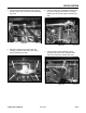
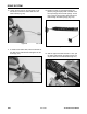
3. Lift up slightly on the neutral centering lever and
align the bushings to the bolt holes and install the
four bolts and nuts and tighten (Fig. 498).
Figure 498 DSC-1252
DRIVE SYSTEM
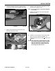
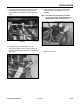
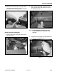
9. Traction control assembly (Fig. 496).
Figure 496 DSC-1256
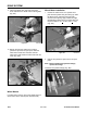
8. Tilt the top of the control assembly forward and
slide the assembly down and out of the control
handle and then out of the unit (Fig. 495).
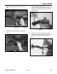
Traction Control Handle Assembly
Installation
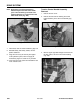
1. Install traction control assembly, tilting the top
of the control assembly forward so the control
handle can be installed onto the drive rod
assembly; do not install the bolt and nut.
2. Install flat washer, spring washer, washer, and
then the bushing on each end of the control
support assembly (Fig. 497).
Figure 495 DSC-1255
Figure 497 DSC-1262
8-22
TX 413 Service Manual
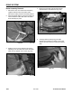
A. RH Return Lever D. LH Return Lever
B. Neutral Switch Stud E. Neutral Centering Cam
C. Neutral Return Spring F. Reverse Lever Asm.
A
D
C
B
E
F