
Service Manual


Rev. 000
TX 413 Service Manual
8-23
DRIVE SYSTEM
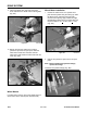
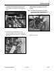
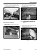
5. Install the right side rod linkage with a bolt
through the bearing rod end, spacer, through the
drive rod assembly and install the nut and tighten
(Fig. 500).
Figure 500 DSC-1264
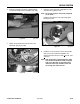
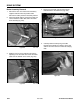
4. Install the left side rod linkage with a bolt through
the bearing rod end, spacer, through the drive
rod assembly and install the nut and tighten (Fig.
499).
Figure 499 DSC-1263
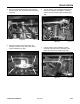
Figure 501 DSC-1247
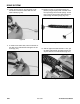
7. Install the rear cover.
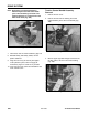
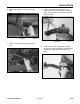
6. Insert the bolt and nut into the traction control
handle assembly and through the drive rod
assembly.
Note: The control handle assembly is slotted,
so you need to align the assembly before
tightening the bolt and nut (Fig. 501).