
Service Manual

Rev. 000
TX 413 Service Manual
8-29
DRIVE SYSTEM
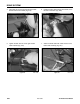
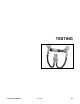
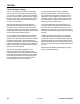
8. Brake Adjustment - Ensure the brake engages
and disengages freely. The brake bars should
both move in and out of the frame. When
disengaged, the brake bar should not protrude
more than 1/2" (12.7mm) out of the frame (Fig.
522).
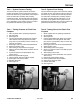
Idler Assembly Removal
Figure 522 DSC-1292
Figure 523 DSC-1291
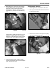
9. Install the battery bracket. Install the battery
and the positive battery cable, then the negative
cable. Install the rear cover.
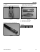
1. Raise engine cover and remove the belt cover.
2. Use a pry bar to relieve idler tension and remove
the drive belt (Fig. 524).
Figure 524 DSC-1293
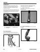
If adjustment is needed, there are two jam nuts
located on the brake cable, next to the cable
bracket on the left inside of the frame (Fig. 523).
Loosen the jam nuts to adjust the brake bars.
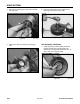
3. Loosen the set screws on the engine drive pulley
and remove the pulley (Fig. 525).
Figure 525 DSC-1294