
Service Manual

Rev. 000
DRIVE SYSTEM
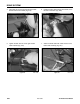
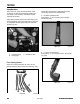
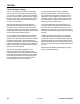
4. Remove the retaining ring on the end of the idler
arm (Fig. 526).
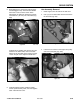
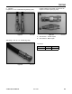
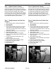
6. Remove the idler pulley from the idler arm by
removing the bolt and nut (Fig. 528).
Figure 526 DSC-1295
Figure 528 DSC-1298
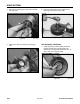
5. Remove the idler arm and torsion spring (Fig.
527).
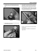
1. Install idler pulley by first installing the spacer
between the idler arm and idler pulley, bolt,
washer and nut. Tighten bolt and nut to 27 - 33
ft-lbs. (36.6 - 44.7 Nm) (Fig. 529).
Figure 527 DSC-1297
Figure 529 DSC-1299
8-30
TX 413 Service Manual
Idler Assembly Installation