
Service Manual

TX 413 Service Manual
9-5
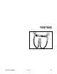
TESTING
Rev. 000
This test checks the system pressure for both the
auxiliary and loader circuits. Components involved in
this test are Gear Pump, Loader Valve, Power Beyond
Valve at Loader Valve, Auxiliary Valve, auxiliary
couplers and hoses. This test will verify that pressure
is or is not the reason for the problem in the hydraulic
circuit. Depending on test results, Test 5 may need to
be performed to determine system problem.
This test checks the system fl ow for both the auxiliary
and loader circuits. Components involved in this test
are Gear Pump, Loader Valve, Power Beyond Valve
at Loader Valve, Auxiliary Valve, auxiliary couplers
and hoses. This test will verify that fl ow is or is not
the reason for the problem in the hydraulic circuit.
Depending on test results tests 3 & 4 may need to be
performed to determine the system problem.
Test 2 - System Flow Testing
Test 1 - System Pressure Testing
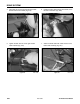
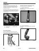
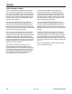
Test 1 - Testing Pressure at Flush Face
Couplers
1. Warm hydraulic fluid to operating temperature
2. Set park brake.
3. Shut engine off.
4. Connect pressure/flow test gauge into couplers.
Have restrictor valve fully open on flow meter
(may have to cycle auxiliary valve to remove any
pressure at couplers).
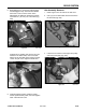
5. Start engine and run at full recommended RPM.
6. Stroke the auxiliary valve.
7. Take reading of the pressure at the gauge.
8. Adjust to recommended psi/bar at loader valve as
necessary.
9. If pressure doesn't meet specification, then
perform Test 5.
10. Disconnect pressure/flow gauge.
11. Check hydraulic fluid level; add as needed.
12. Start engine and check for leaks.
13. Release park brake.
14. Shut engine off.
Figure 540 DSC-1528
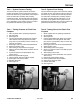
Figure 541 DSC-1528
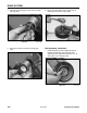
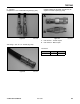
1. Warm hydraulic fluid to operating temperature.
2. Set park brake.
3. Shut engine off.
4. Connect pressure/flow test gauge into couplers.
Have restrictor valve fully open on flow meter
(may have to cycle auxiliary valve to remove any
pressure at couplers).
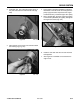
5. Start engine and run at full recommended RPM.
6. Stroke auxiliary valve.
7. Take reading of flow at the gauge.
8. Slowly turn restrictor valve in until 2650 psi (183
bar) is obtained.
9. Take reading at flow meter.
10. If flow does not meet specification, then perform
Tests 3 and 4.
11. Disconnect pressure/meter gauge.
12. Check hydraulic fluid; add as needed.
13. Start unit and check for leaks.
14. Release park brake.
15. Shut engine off.
Test 2 - Testing Flow at the Flush Face
Couplers