
Service Manual

TESTING
9-6
TX 413 Service Manual
Rev. 000
1. Warm hydraulic fluid to operating temperature.
2. Set park brake.
3. Shut engine off.
4. Use a drain pan under the gear pump.
5. Remove hydraulic line from pump outlet to loader
valve inlet.
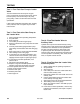
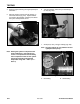
6. Connect pressure/flow gauge between pump
outlet fitting and the loader valve inlet fitting (Fig.
542).
7. Start engine and run at full recommended RPM.
8. Take reading of flow at the gauge.
9. If pump does not meet flow specification, then
check for suction hose restriction, pump pulley
slippage and then repair or replace gear pump.
10. If pump does meet flow specification, then
perform Test 4.
11. Disconnect pressure/flow gauge.
12. Replace o-rings and reinstall hydraulic line
between pump outlet and loader valve inlet.
13. Check hydraulic fluid and add as needed.
14. Start unit and check for leaks.
15. Remove drain pans.
16. Release park brake.
17. Shut engine off.
Test 3 - Flow Test at the Gear Pump to
the Loader Valve
This test measures the fl ow output of the gear
pump. Components involved are fl ow meter, suction
hose and pump. This test will verify if the pump,
pump pulley, or belt is at fault if fl ow does not meet
specifi cation.
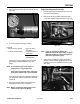
If fl ow meets specifi cation the loader valve, auxiliary
valve, steel line, hose or couplers may be at fault.
Perform test 4.
Hydraulic fl ow output can be determined by turning
restrictor valve on test gauge inward until specifi cation
is obtained. If the fl ow does not meet specifi cation
and test 3 has been performed, then loader valve
or power beyond valve will need to be repaired or
replaced. If fl ow tests to specifi cation the loader valve
is not the problem. The auxiliary valve, hoses, steel
lines, or couplers could be at fault.
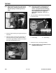
Test 4 - Flow Test Loader Valve to
Auxiliary Valve
Test 3 - Flow Test Gear Pump to Loader
Valve
Figure 542 DSC-1525
1. Warm hydraulic fluid to operating temperature.
2. Set park brake.
3. Shut engine off.
4. Use 2 drain pans. Place one under loader valve
and one under auxiliary valve.
5. Disconnect hydraulic line from loader valve to the
auxiliary valve.
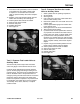
6. Connect pressure/flow gauge from loader valve
to the auxiliary valve (Fig. 543).
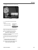
7. Start engine and run at full recommended RPM.
8. Take reading of flow at the gauge.
9. Slowly turn restrictor valve in until 2650 psi (183
bar) is obtained.
10. If flow does not meet specification, check for any
hydraulic line restrictions, then repair or replace
loader valve.
Test 4 - Flow Test from the Loader Valve
to Auxiliary Valve