
Service Manual

TX 413 Service Manual
9-9
TESTING
Rev. 000
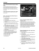
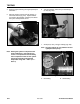
1. Lift and support the unit so tracks are 3 to 4" (7.6
to 10.2cm) off the ground.
2. Disconnect the two output hydraulic lines to the
wheel motor with a 1-1/8" offset wrench (Fig.
547).
Note: Before removing nuts from the hydraulic
fi ttings, place a piece of tape around both
hydraulic lines, so the nut will not slide
down the hydraulic line.
Figure 547 DSC-2926
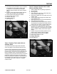
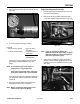
2. Using tie straps, tie strap each hydraulic line away
from the hydraulic fi tting (Fig. 548).
Figure 548 DSC-2928
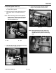
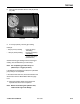
Figure 550 DSC-2932
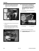
Note: Before performing this test, make sure
the bypass valve is closed on the pump
located below the hydraulic inlet line (Fig.
550).
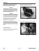
Figure 549 DSC-2930
3. Connect the fl ow tester to the two hydraulic
fi ttings on the hydrostatic pump (Fig. 549).
Left Drive System Flow Test
A. Nuts B. Tape
A
A
B