
Service Manual

TX 413 Service Manual
9-11
TESTING
Rev. 000
9. At 1100 psi (76 bar) note gpm reading.
Example:
• 300 psi (21 bar) reading 8 gpm (30 l/min)
1st reading
• 1100 psi (76 bar) reading 6.5 gpm (24.6 l/min)
2nd reading
1.5 gpm (5.6 l/min)
(the difference)
Subtract the fi rst gpm reading from the second
gpm reading. This will determine your “fl ow
droop”.
Note: The acceptable gpm “fl ow droop” or
(difference) is: 1.5 gpm (5.6 l/min)
If the difference exceeds these values, the
hydrostatic pump droop is not acceptable.
If the values have been met, the issue would be in
the wheel motor. Refer to Wheel Motor Removal,
page 8-16.
10. Disconnect the fl ow tester and reconnect the
hydraulic lines when test is completed.
Note: Before reconnecting the hydraulic lines,
install new O-rings in the fi ttings.
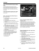
Figure 554 DSC-2942
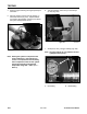
8. Then turn the restriction valve to 1100 psi (76 bar)
(Fig. 554).
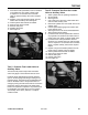
1. Lift and support the unit so tracks are 3 to 4" (7.6
to 10.2cm) off the ground.
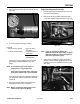
2. Disconnect the two hydraulic output lines with a
1-1/8" offset wrench to the wheel motor (Fig. 555).
Right Drive System Flow Test
Figure 555 0871 rev
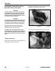
Note: It may be necessary to loosen the
hydraulic lines at the wheel motor to obtain
additional clearance to move the hydraulic
lines at the hydrostatic pump.
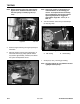
3. Use tie straps to hold the hydraulic lines out of
the way. Connect the fl ow gauge lines to the two
hydraulic ports on the hydrostatic pump (Fig. 556,
rear view).
Figure 556 DSC-2946