
Service Manual


ATTACHMENTS
10-5TX 413 Service Manual
Rev. 001
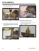
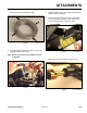
2. Install the gauge teeth on the outside edges of the
auger bit (Fig. 013).
Fig 013 CLR DSC-0383
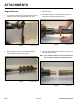
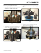
1. Replace the new teeth in their correct location on
theaugerbit.Torquethelocknutsto88+ 12 ft-lbs.
(119 + 16 Nm) (Fig. 012).
Note: It is good practice when replacing teeth to
also replace the carriage bolts and nuts.
Fig 012 CLR DSC-0222
Auger Tooth Replacement
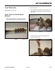
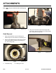
Fig 015 CLR DSC-0101
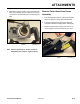
1. Remove coupler and nipple connectors from the
loader arm (Fig. 015).
Disassemble Auger Power Head
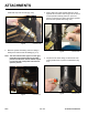
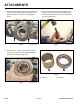
3. The wisdom tooth is installed next to the gauge tooth
on the inside edge closest to the auger shaft (Fig.
014).
Fig 014 CLR DSC-0382
4. Torquenutsto150+ 15 ft-lbs. (203 + 20 Nm).