
Service Manual


ATTACHMENTS
10-10 TX 413 Service Manual
Rev. 001
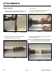
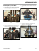
Fig 032 CLR DSC-0130
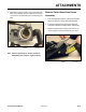
8. Using a 1/8” hex wrench, remove the three hex head
screws from the bearing protector plate (Fig. 032).
Remove the plate to access the 2 bearings and
spacer.
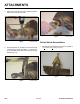
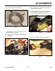
10. Using a hammer and punch, go around the circum-
ferenceofthebearingtodrivetherstbearingout.
With the bearing removed, the spacer will slide out
(Fig. 034 and Fig. 035).
Fig 034 CLR DSC-0132
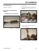
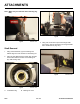
9. Remove the 1/2” x 2-3/4” bolt securing the auger
housing to the cradle. Swing the auger housing so
the shaft end is facing up (Fig. 033).
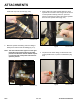
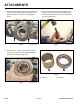
A. Spacer B. Bearing
Fig 033 CLR DSC-0138
Fig 035 DSC-134
A B