
Service Manual


ATTACHMENTS
10-16 TX 413 Service Manual
Rev. 001
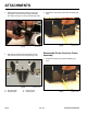
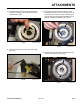
6. Remove any dirt or debris from the auger shaft and
slide it into the auger housing (Fig. 054).
Fig 054 CLR DSC-0161
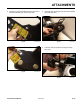
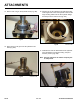
7. Remove the 1/2” x 2-3/4” bolt securing the auger
housing. Rotate the shaft down and lower arm.
Insert the new bearing lockwasher onto the auger
shaft. Make sure the tangs are facing out towards
the bearing nut (Fig. 055).
Fig 055 CLR DSC-0163
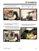
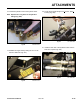
Fig 056 CLR DSC-0165
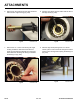
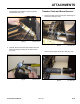
Fig 057 CLR DSC-0179
9. With the auger shaft pointing down on a secure
surface, place a 7/8” round stock through the shaft to
preventitfromturningwhentorquingthebearingnut
(Fig. 057).
8. Align the inner tab of the lock washer with the slot on
the auger shaft (Fig. 056).