
Service Manual


ATTACHMENTS
10-18 TX 413 Service Manual
Rev. 001
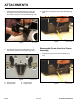
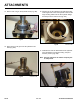
14. Place a new o-ring on the hydraulic motor (Fig. 062).
Fig 062 CLR DSC-0194
15. Place the key in the groove of the hydraulic motor
shaft (Fig. 063).
Fig 063 CLR DSC-0198
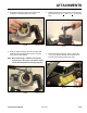
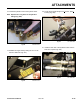
Fig 064 CLR DSC-0199
16. Align the key of the hydraulic motor with the keyway
of the auger shaft. Lower the hydraulic motor into the
auger housing. Make sure the 90
o
hydraulicttings
face away from the traction unit (Fig. 064).
Fig 065 CLR DSC-0210
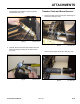
17. Install the four 3/8” hex head bolts into the hydraulic
motorandfastentotheaugerhousing.Torqueto
25 ft-lbs. (34 Nm) (Fig. 065).
Note: Using an extension can reduce torque by one
or two pounds.