
Service Manual


ATTACHMENTS
10-30 TX 413 Service Manual
Rev. 001
Fig 109 CLR DSC-0341
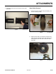
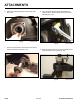
4. Press or drive spacer.
Note: Spacer stepped side faces up (Fig. 109).
Fig 108 CLR DSC-0337
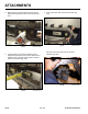
3. The shaft seal is installed with the step facing down
toward the bearing. The green coating facing up.
Press or drive the shaft seal until fully seated (Fig.
108).
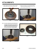
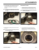
5. After the shaft side is assembled, turn the boom
mount over onto its side and install bearing into the
motor side (Fig. 110).
Fig 110 CLR DSC-0342
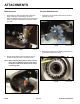
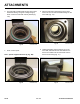
Fig 111 CLR DSC-0343
6. Holding the bearing into the bearing cup on the
motor side, slide the trencher drive shaft into the
boom mount. Make sure the shaft seats onto the
boom mount housing (Fig. 111).