
Service Manual


ATTACHMENTS
10-35TX 413 Service Manual
Rev. 001
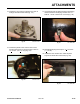
Fig 128 CLR DSC-0374
26. Slide the spoils auger onto the trencher shaft. Install
screw and nut into one of the two holes according to
chainwidth.Torqueto105+ 11 ft-lbs. (142 + 15 Nm)
(Fig. 128).
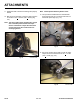
Fig 127 CLR DSC-0373
25. Hold the other side of the screw with a wrench and
torquethesupportplateboltsto150+ 15 ft-lbs.
(203 + 20 Nm) (Fig. 127).
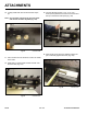
27. Ifapplicable,installsafetybarandtorquethethree
screws and nuts to 210 + 20 ft-lbs. (284 + 27 Nm)
(Fig. 129).
Fig 129 CLR DSC-0376
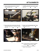
28. Remove caps and install hydraulic hoses onto the
hydraulicmotor.Torquehosettingto59+ 7 ft-lbs.
(80 + 9 Nm) (Fig. 130).
Fig 130 CLR DSC-0377
Note: If motor ttings are removed and replaced,
torque to 85 + 10 ft-lbs. (115 + 13 Nm).
29. Start traction unit and test trencher in both
directions. Check for leaks.