
Service Manual


Rev. 000
TX 413 Service Manual
4-9
ENGINE
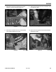
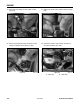
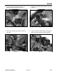
1. Move the choke control on the dash to full
position, then back the choke control so it is
approximately 1/16" (1.6mm) away from the front
edge of the slot (Fig. 047).
Figure 047 DSC-1123
Figure 048 DSC-1124
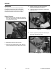
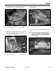
9. Apply an anti-seize compound to the engine
crankshaft and key. Apply a medium strength
threadlocking material to the threads of the set
screws and install the engine drive pulley. Using
a straight edge, align the engine drive pulley
to the lower hydrostatic pump pulley; with the
engine bolts loose, you can move the engine to
help align the pulley (Fig. 045).
Note: The belt idler pulley will need to be
retracted while aligning the engine pulley
with the hydrostatic pump pulley.
Figure 045 DSC-1119
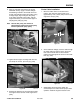
10. Tighten all four engine mounting bolts and nuts
and torque to 18 ft-lbs. (24.4 Nm) (Fig. 046).
Figure 046 DSC-1114
Choke Cable Installation
2. At the carburetor linkage, insert the cable through
the cable clamp and into the hole in the choke
lever. Pull the choke lever to the full choke
position and hold; tighten the screw on the choke
lever (Fig. 048).
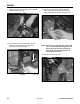
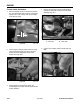
3. While holding the choke lever, tighten the
screw/clamp for the cable. Test for proper choke
operation. Install the engine air cleaner cover.
11. Recheck the alignment of the engine drive pulley,
then tighten the set screws on the engine drive
pulley.