
Service Manual


Rev. 000
ENGINE
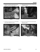
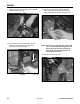
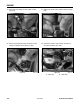
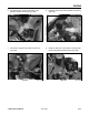
4. Connect the blue wire onto the spade terminal
and the two red wires to the post on the starter
assembly (Fig. 051).
Figure 051 DSC-1111
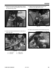
5. Connect the oil switch, black to white wire (Fig.
052).
Figure 052 DSC-1107
4-10
TX 413 Service Manual
A - Blue wire B - Red wires
A
A
B
B
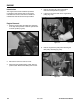
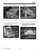
1. Move the throttle control on the dash to full posi-
tion, then back the throttle control so it is approxi-
mately 1/16" (1.6mm) away from the front edge
of the slot (Fig. 049).
Figure 049 DSC-1126
Figure 050 DSC-1127
Throttle Cable Installation
2. On the engine, insert the cable under the clamp;
move the engine throttle lever to the full open
position and hold; tighten the screw on the
throttle lever (Fig. 050).
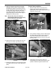
3. While holding the throttle lever, tighten the
screw/clamp for the cable. Test for proper throttle
control operation.