
Service Manual


Rev. 000
ENGINE
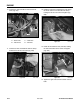
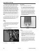
Figure 066 DSC-1095
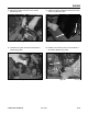
4. Remove the two bolts and nuts retaining the tank
straps located at the top of the fuel tank (Fig.
067).
Figure 067 DSC-1131
4-14
TX 413 Service Manual
Fuel Tank Removal
1. Start the unit, raise the lift arm to the fully raised
position and install the hydraulic cylinder lock in
the lift cylinder. Shut engine off.
2. Remove the rear cover and remove the negative
battery cable.
3. Remove the fuel tank vent hose from the oil filter
bracket (Fig. 066).
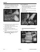
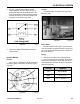
19. Install bolt and nut located at the bottom of the
exhaust deflector and tighten the bolt (Fig. 065).
Then tighten the rest of the bolts in the front
grille, the right side tank bracket, and on the
exhaust deflector.
Figure 065 DSC-1090
20. Install the drive belt; refer to Drive Belt Removal
and Installation, pages 8-2 and 8-3.
21. Install the battery. Connect the positive cable,
then the negative cable.
22. Install the belt cover and rear cover.
23. Remove the hydraulic cylinder lock in the lift
cylinder.
24. Start the unit and lower the lift arm. Check the
engine high engine RPM. The engine RPM
should be at 3600 + 150 RPM.