
Service Manual


Rev. 000
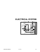
There are two primary current paths when the
ignition switch is in the "START" position. (1) Current
flows from the ignition switch to both the coil and
contact terminals of the start relay. From the coil
terminal of the start relay, current flows to the neutral
detent (located on the Auxiliary Power Valve) to the
contact terminal of the kill relay. Also, current flows to
the engine starter. (2) At the same time, current flows
to a neutral switch, (located on the control handle
assembly) and to the engine fuel solenoid. From the
neutral switch current flows to the coil terminal of the
kill relay, which activates and takes the electronic
ignition wire off of ground to allow the engine to have
spark.
The following electrical section covers most of the
electrical components used on the TX 413. It covers
each electrical component's purpose, how it works,
testing procedures and location on the unit.
ELECTRICAL SYSTEM
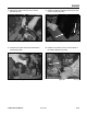
A relay is an electrically actuated switch.
1. Coil: Terminals 85 and 86 are connected to a
coil. Applying 12 volts to these terminals ener-
gizes the coil turning it into an electromagnet.
2. Switch: Terminals 30, 87 and 87a are actually
part of a single pole, double throw (SPDT) switch.
Terminal 30 is the common lead. The switch is
spring loaded so that 30 and 87a are connect
when the coil is not energized. When the coil is
energized, the switch is "thrown" and 30 and 87
are connected (Fig. 084).
Figure 084 MVC-0671X
Relay
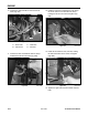
The TX 413 uses two relays to direct current flow
to different areas of the unit. The two relays are the
kill relay and the start relay. Electrically, they both
operate the same.
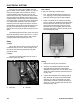
Figure 083 DSC-0753
5-2
TX 413 Service Manual
Purpose
How It Works
The relays are located behind the rear cover, in
back of the hoses (Fig. 083).
Location
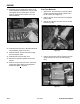
1. Disconnect the relay from the harness.
2. Verify the coil resistance between terminals
85 and 86 with a multimeter (ohms setting).
Resistance should be from 70 to 90 ohms. There
should be continuity between terminals 87a and
30 (Fig. 108).
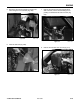
3. Connect the multimeter (ohms setting) leads to
relay terminals 30 and 87. Ground terminal 86
and apply +12 VDC to terminal 85. The relay
should make and break continuity terminals 30
and 87 as 12 VDC is applied and removed from
terminal 85 (Fig. 108).
Testing
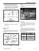
A
A
A. Start relay B. Kill relay
B
B