
Service Manual


Rev. 000
TX 413 Service Manual
5-3
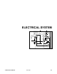
ELECTRICAL SYSTEM
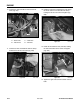
5. Disconnect voltage and multimeter leads from
relay terminals.
Figure 085 xl relay
4. Connect multimeter (ohms setting) leads to
relay terminals 30 and 87a. Apply +12 VDC to
terminal 85. With terminal 86 still grounded, the
relay should break and make continuity between
terminals 30 and 87a as 12 VDC is applied and
removed from the terminal (Fig. 085).
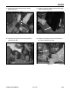
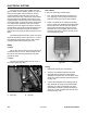
Ignition Switch
This component provides the proper switching for
the starter, ignition, accessories, and safety circuits
(Fig. 086).
Figure 086 mvc-166 art
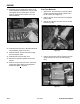
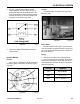
Purpose
The ignition switch is located on the top control
panel (Fig. 087).
Figure 087 DSC-0750
Location
Detents inside the switch give it 3 positions: OFF,
RUN, and START. The START position is spring load-
ed so the cylinder automatically returns to RUN once
the key is released.
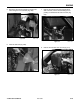
How It Works
1. Disconnect the switch from the wiring harness.
2. Verify that continuity exists between the terminals
listed for the switch position. Verify that there is NO
continuity between terminals not listed for the switch
position (Figure 086).
Testing
Position Condition
Off No continuity
Start B + I + S
Run B + I + A and X + Y