
Service Manual


Rev. 000
ELECTRICAL SYSTEM
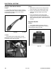
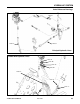
Auxiliary Power Neutral Switch
3. The normally closed ball type switch is used on
the auxiliary power valve. This is a safety type switch
to make sure the auxiliary power valve is in the
neutral detent (Fig. 088).
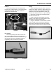
1. Disconnect the switch from the wiring harness.
Leave the switch in the Auxiliary Power Valve.
2. Using a VOM multimeter (ohms setting) there
should be continuity between the two wire
terminals.
3. Leave the Multimeter (ohms setting) leads
connected to the two wire terminals. Move the
auxiliary power valve handle to either the reverse
flow or forward flow position. There should be NO
continuity.
Figure 088 MVC-0866X
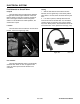
The auxiliary power neutral switch is located
behind the rear cover, on the left side of the unit, on
the auxiliary power valve (Fig. 089).
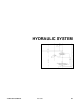
Regulator-Rectifier
The regulator-rectifier changes AC stator to
DC and regulates the charging current, to prevent
overcharging the battery (Fig. 090).
Figure 089 DSC-0758
Figure 090 MVC-0870X
5-4
TX 413 Service Manual
Location
Purpose
Testing
Purpose