
Service Manual


Rev. 000
TX 413 Service Manual
5-5
ELECTRICAL SYSTEM
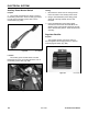
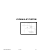
The regulator-rectifier is located behind the rear
cover, in back of the hoses (Fig. 091).
Location
Figure 091 DSC-0753
This regulator-rectifier, like many others, must
be connected to the battery to function. Once the
voltage level of the battery exceeds approximately
14 volts, the regulator-rectifier stops sending current
to the battery and no charging takes place. When
the voltage again drops below the specified level,
the regulator-rectifier sends the current back to the
battery.
How It Works
1. Check the battery before checking the voltage
regulator. The battery must be fully charged
and in good condition for the voltage regulator
to operate properly. (The voltage across the the
battery terminals should be 13.6 volts or more.)
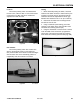
2. Using a multimeter set to DC volts, insert the
positive probe of the meter into either A or B
terminal violet wire. The negative probe should
go to ground (C) or to the negative battery cable.
Check the reading on the meter. Start the unit
and operate the engine at full throttle. You should
see an increase in DC voltage and should read
13.6 to 14 DC voltage or more. System is OK.
Testing
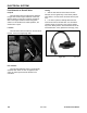
3. If not, check stator output. Using a multimeter
set to AC volts, connect a probe to D and E
terminal (grey wire). Start the unit and operate at
full throttle. The AC voltage should be 27 volts or
more. If not, the stator is bad. Stator resistance
can also be checked - it should be 0.16 - 0.24
Ohms. If OK, proceed to step 4.
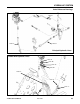
4. Shut the engine OFF. Disconnect the electrical
connector from the regulator-rectifier. Set
the multimeter to read Ohms. The resistance
measurements are:
D and A, C, E infinity
E and A, C infinity
A and D, E 1 - 200 KΩ
A and C 0.1 - 100 KΩ
C and D, E 0.1 - 50 KΩ
(Fig. 092).
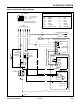
Figure 092 MVC-0872X
B
A
C
D
E
A. Violet Wire (B+ to fuse 25A)
B. Violet Wire (B+ to fuse 25A)
C. Black Wire (Ground)
D. Grey Wire (AC from Charge Coil Engine)
E. Grey Wire (AC from Charge Coil Engine)