
Service Manual


Rev. 000
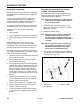
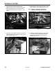
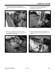
10. Disconnect the hydraulic case drain line,
(page 6-2, Ref. 2), from the bottom of the right
drive hydrostatic pump, at the T-fitting that is
connected to the reservoir tank (Fig. 111, rear
view).
Figure 111 DSC-0869a
HYDRAULIC SYSTEM
6-8
TX 413 Service Manual
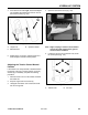
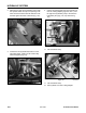
11. Disconnect the hydraulic case drain line from the
upper hydrostatic pump, (page 6-2, Ref. 5), and
remove the line (Fig. 112).
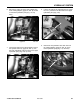
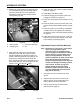
13. Position the control handle so you can install
a 1/4" Allen wrench into the Allen head bolt
retaining the rod linkage to the pump lever
assembly, (Fig. 114).
Figure 112 DSC-0870
Figure 114 DSC-0874
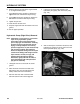
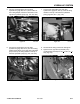
12. Disconnect the two hydraulic lines to the wheel
motor, (page 6-2, Ref. 3A and 3B), (Fig. 113).
Note: It may be necessary to loosen the
hydraulic lines at the wheel motors.
Figure 113 DSC-0871