
Service Manual


Rev. 000
TX 413 Service Manual
6-13
HYDRAULIC SYSTEM
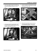
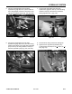
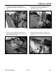
7. Remove the inlet hydraulic line, (page 6-2, Ref.
7) from the side of the left drive hydrostatic pump
(Fig. 131).
Figure 131 DSC-0894
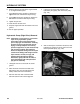
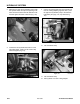
6. Disconnect the case drain hydraulic line (page
6-2, Ref 5), from the top of the left drive
hydrostatic pump (Fig. 130).
Figure 130 DSC-0893
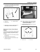
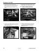
5. With a 1-1/8" offset open end wrench, remove
both the left drive hydraulic motor lines (page 6-2,
Ref. 4A and 4B), (Fig. 129).
Figure 129 DSC-0892
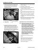
Figure 128 DSC-0891
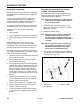
4. Loosen the two set screws located on the
hydrostatic pump pulley and remove pulley (Fig.
128).