
Service Manual

HYDRAULIC SYSTEM
6-20
TX 413 Service Manual
Rev. 000
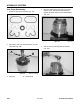
Hydraulic Gear Pump Installation
Note: As a reminder, prior to connecting the
hydraulic lines, the O-rings should be
replaced with new ones and lightly
lubricated with petroleum jelly.
1. When installing a new gear pump, make sure the
hydraulic fittings are installed properly; refer to
the Gear Pump Fittings section on page 6-21.
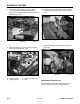
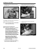
2. Apply anti-seize compound on the gear pump
shaft. Slide the hydraulic suction line on the fitting
onto the front of the gear pump hose (Fig. 154).
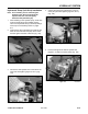
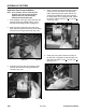
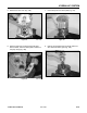
4. Apply a medium strength threadlocking material
to the set screws and install in the gear pump
pulley. Slide the gear pump pulley, with the set
screws facing toward the gear pump and leave
the pulley loose, on the pump gear shaft. Tighten
the pump mounting screws to 18 + 3 ft-lbs. (24 +
4 Nm) (Fig. 156).
Figure 156 DSC-0922
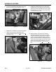
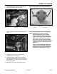
5. Install gear pump pulley. Position the pulley all
the way back, up against the shaft shoulder, and
tighten the set-screws to 215 + 35 in-lbs. (24 + 4
Nm) (Fig. 157).
Figure 157 DSC-0910
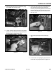
3. Install the gear pump with two mounting screws
and nuts into the frame, leaving the bolts and
nuts loose (Fig. 155).
Figure 155 DSC-0921
Figure 154 DSC-0920