
Service Manual


Rev. 000
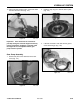
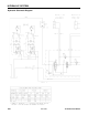
4. Lubricate and install the back-up ring in the
groove of the seal (Fig. 177).
Figure 177 DSC-1482
HYDRAULIC SYSTEM
6-26
TX 413 Service Manual
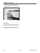
7. Lubricate and install the driven gear (Fig. 180).
Figure 180 DSC-1486
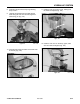
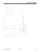
5. Install the thrust plate to the front cover (seals
facing the front cover).
NOTE: Match up the alignment marks on the
front cover and thrust plate (Fig. 178).
Figure 178 DSC-1483
6. Lubricate and install the drive shaft and gear (Fig.
179).
Figure 179 DSC-1484