
Service Manual


Rev. 000
HYDRAULIC LIFT ASSEMBLY
7-4
TX 413 Service Manual
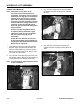
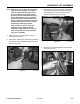
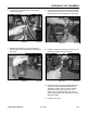
9. Remove two of the three retaining bolts that
mount the hydraulic lift valve to the frame. There
are three access holes located in the frame (Fig.
193).
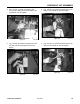
Loader Valve Installation
Note: As a reminder, prior to connecting the
hydraulic lines, the O-rings should be
replaced with new ones and lightly
lubricated with petroleum jelly.
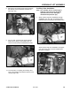
1. Install the valve and align the mounting holes.
Install the three bolts and tighten (Fig. 195).
Figure 193 DSC-0936
Figure 195 DSC-0936
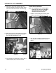
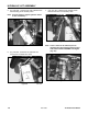
10. While removing the last bolt holding the hydraulic
lift valve, support the valve and lower the valve
out of the tower assembly (Fig. 194).
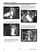
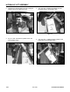
2. (Fig. 196, Ref. I) Install the hydraulic hose from
auxiliary valve to the hydraulic lift valve and
tighten.
Figure 194 DSC-0937
Figure 196 DSC-0935
11. For information on repairing the lift valve, refer to
Lift Valve Repair, page 7-47 of this manual.