
Service Manual


Rev. 000
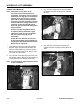
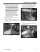
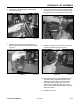
7. (Fig. 201, Ref. B) Install the hydraulic hose to the
fitting on the hydraulic lift valve and tighten.
9. Start the unit and check the hydraulic fittings for
any leaks. Operate the loader valve up, down,
and tilt to purge any air out of the system. Install
the belt cover and the rear cover.
Figure 201 DSC-0927
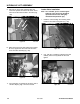
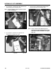
8. (Fig. 202, Ref. A) Install the hydraulic hose to the
fitting on the hydraulic lift valve and tighten.
Auxiliary Valve Removal
Figure 202 DSC-0925
HYDRAULIC LIFT ASSEMBLY
7-6
TX 413 Service Manual
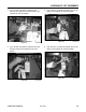
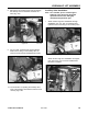
The hose connections at the auxiliary valve on
units with serial numbers 240000100 - 240000200
are close to each other. To obtain enough room to
remove the upper hose, the lower hose and fitting
needs to be removed (Fig. 203).
Figure 203 DSC-0944
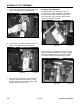
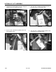
Upper hose fitting on the auxiliary valve on units with
serial numbers from 240000201 and higher is longer.
This will give additional space to remove the upper
hose without removing the lower fitting (Fig. 204).
Figure 204 DSC-1039