Form No. 3360-118 Rev A Dingo® TX 525 Compact Utility Loader Model No. 22319—Serial No. 280000301 and Up Model No. 22320—Serial No. 280000301 and Up G004222 Register at www.Toro.com.
Warning CALIFORNIA Proposition 65 Warning Diesel engine exhaust and some of its constituents are known to the State of California to cause cancer, birth defects, and other reproductive harm. Because in some areas there are local, state, or federal regulations requiring that a spark arrester be used on the engine of this machine, a spark arrester is available as an option. If you require a spark arrestor, contact your Authorized Service Dealer.
Contents Servicing the Battery........................................... 32 Drive System Maintenance ..................................... 35 Servicing the Tracks............................................ 35 Cooling System Maintenance .................................. 38 Servicing the Cooling System.............................. 38 Belt Maintenance.................................................... 39 Checking the Condition of the Hydraulic Pump Belt ...................................................
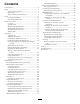
Safety • Inspect the area where the equipment is to be used and remove all objects such as rocks, toys, and wire which can be thrown by the machine. • Use extra care when handling fuels. They are flammable and vapors are explosive. – Use only an approved container – Never remove the fuel cap or add fuel with the engine running. Allow the engine to cool before refueling. Do not smoke. – Never refuel or drain the machine indoors.
• Read all attachment manuals. • Ensure that the area is clear of other people before operating the traction unit. Stop the traction unit if anyone enters the area. • Never leave a running traction unit unattended. Always lower the loader arms, stop the engine, set the parking brake, and remove the key before leaving. • Do not exceed the rated operating capacity, as the traction unit may become unstable which may result in loss of control. • Do not carry a load with the arms raised.
– Keep container nozzle in contact with the tank during filling. • Let the engine cool before storing and do not store near flame. • Do not store fuel near flames or drain indoors. • Park the machine on level ground. Never allow untrained personnel to service the machine. • Use jack stands to support components when required. • Carefully release pressure from components with stored energy. • Disconnect the battery before making any repairs. Disconnect the negative terminal first and the positive last.
Slope Chart 7
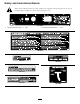
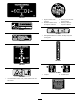
Safety and Instructional Decals Safety decals and instructions are easily visible to the operator and are located near any area of potential danger. Replace any decal that is damaged or lost. 112-2469 1. Operator’s Manual location 2. Slow 3. Continuous variable setting 4. Fast 108-4674 NECTING COUPLERS. WHEN CONNECTING COUPLERS. E WEAR SHOULD BE WORNPROTECTIVE WEAR SHOULD BE WORN T. MAY BE HOT. C COUPLERS HYDRAULIC COUPLERS NECTING COUPLERS. WHEN CONNECTING COUPLERS.
106-9453 106-6755 1. Engine coolant under pressure. 2. Explosion hazard—read the Operator’s Manual. 3. Warning—do not touch the hot surface. 4. Warning—read the Operator’s Manual. 80-8040 93-6681 1. Cutting/dismemberment—hazard, fan-stay away from moving parts. 105-8432 108-4671 108-4670 93-9084 1. Lift point 2. Tie-down point 104-9983 1. Hot surface/burn hazard—stay a safe distance from the hot surface.
114-9600 1. Read the Operator’s Manual. Battery Symbols Some or all of these symbols are on your battery 1. Explosion hazard 2. No fire, open flame, or smoking. 3. Caustic liquid/chemical burn hazard 4. Wear eye protection 5. Read the Operator’s Manual. 115-0790 10 6. Keep bystanders a safe distance from the battery. 7. Wear eye protection; explosive gases can cause blindness and other injuries 8. Battery acid can cause blindness or severe burns. 9.
Setup 3. When the battery is fully charged, unplug the charger from the electrical outlet, then disconnect the charger leads from the battery posts (Figure 3). 1 4. Close the rear access cover. 2 Charging the Battery No Parts Required Checking Fluid Levels Procedure No Parts Required Warning Procedure CALIFORNIA Proposition 65 Warning Battery posts, terminals, and related accessories contain lead and lead compounds, chemicals known to the State of California to cause cancer and reproductive harm.
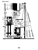
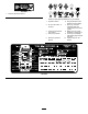
Controls Product Overview Become familiar with all the controls (Figure 5) before you start the engine and operate the traction unit. Figure 5 1. Auxiliary hydraulics lever 2. Key switch 3. Hour meter 4. Fuel gauge 5. Indicator lights and glow plug switch 6. Throttle lever 7. Loader arm/attachment tilt lever 8. Parking brake lever 9. Reference bar 10. Traction control Key Switch The key switch, used to start and stop the engine, has three positions: off, run, and start.
Traction Control G008131 Figure 9 Figure 6 • To turn left, rotate the traction control counterclockwise (Figure 10). 1. Reference bar (does not move to give you a reference point and a fixed handle to hold while operating the traction unit) 2. Traction control (moves to control the machine) • To move forward, move the traction control forward (Figure 7). G008132 Figure 10 • To stop, release the traction control (Figure 6).
Note: The traction unit may roll slightly before the brakes engage in the drive sprocket. Figure 13 Figure 11 1. Lower the loader arms 2. Raise the loader arms 3. Tilt the attachment rearward 4. Tilt the attachment forward 5. Detent (Float) position To release the brake, push the lever forward and then right, into the notch. Fuel Gauge By moving the lever to an intermediate position (such as, forward and left), you can move the loader arms and tilt the attachment at the same time.
Engine Coolant Temperature Light Glow Plug Switch If the engine coolant gets too hot, this light illuminates and an audible alarm sounds. If this happens, stop the engine and allow the traction unit to cool. Check the coolant level when the engine has fully cooled. Press and hold this switch for 10 seconds to activate the glow plugs before starting the engine. Glow Plug Light The hour meter displays the number of hours of operation that have been logged on the traction unit.
Stability Data The following tables list the maximum slope recommended for the traction unit in the positions listed in the tables. Slopes over the listed degree may cause the traction unit to become unstable. The data in the tables assume that the loader arms are fully lowered; raised arms may affect the stability. In each attachment manual is a set of three stability ratings, one for each hill position.
Operation • The blended fuel composition should meet ASTM D975 or EN590. Note: Determine the left and right sides of the machine from the normal operating position. • Painted surfaces may be damaged by biodiesel blends. Important: Before operating, check the fuel and oil level, and remove debris from the traction unit. Also, ensure that the area is clear of people and debris. You should also know and have marked the locations of all utility lines.
Checking the Engine Oil Level Service Interval: Before each use or daily 1. Park the traction unit on a level surface, lower the loader arms, and stop the engine. 2. Remove the key and allow the engine to cool. 3. Open the hood. 4. Clean around the oil dipstick (Figure 16). In certain conditions during fueling, static electricity can be released causing a spark which can ignite the fuel vapors. A fire or explosion from fuel can burn you and others and can damage property.
Use 10W-30 or 15W-40 detergent, diesel engine oil (API service CH-4 or higher). 1. Remove the attachment, if one is installed; refer to Removing an Attachment. 2. Park the traction unit on a level surface, lower the loader arms, and fully retract the tilt cylinder. 3. Stop the engine, remove the key, and allow the engine to cool. 4. Open the hood. 5. Clean the area around the filler neck of the hydraulic tank (Figure 17). Figure 18 1. Filler neck 2. Dipstick 7.
Checking, Adding, and Bleeding the Engine Coolant Service Interval: Before each use or daily Clean debris off of the screen, oil cooler, and front of the radiator daily and more often if conditions are extremely dusty and dirty The cooling system is filled with a 50/50 solution of water and permanent ethylene glycol antifreeze. Check the level of coolant in the expansion tank at the beginning of each day before starting the engine.
F. Close the top coolant bleed valve (Figure 20). G. Pour coolant into the coolant filler neck until the coolant level comes into the filler neck (Figure 20). H. Install the coolant fill cap (Figure 20). I. Add coolant into the expansion tank until it reaches the Full line on the side of the tank (Figure 20). 3. Install the expansion tank cap.
between attempts. Failure to follow these instructions can burn out the starter motor. 3. Using a wrench, turn the tow valves on the hydraulic pumps twice counter-clockwise (Figure 22). 6. Move the throttle lever to desired setting. Important: If the engine is run at high speeds when the hydraulic system is cold (i.e., when the ambient air temperature is near freezing or lower), hydraulic system damage could occur.
operating characteristics of the traction unit. The warranty of the traction unit may be voided if used with unapproved attachments. 1 Important: Before installing the attachment, ensure that the mount plates are free of any dirt or debris and that the pins rotate freely. If the pins do not rotate freely, grease them. 3 1. Position the attachment on a level surface with enough space behind it to accommodate the traction unit. 2 2. Start the engine. G004182 3. Tilt the attachment mount plate forward.
6. Push the attachment male connector into the female connector on the traction unit. Note: When you connect the attachment male connector first, you will relieve any pressure built up in the attachment. Hydraulic fluid escaping under pressure can penetrate skin and cause injury. Fluid injected into the skin must be surgically removed within a few hours by a doctor familiar with this form of injury or gangrene may result.
Important: Connect the attachment hoses together to prevent hydraulic system contamination during storage. 6. Install the protective covers onto the hydraulic couplers on the traction unit. 7. Start the engine, tilt the mount plate forward, and back the traction unit away from the attachment. Securing the Traction Unit for Transport When transporting the traction unit on a trailer, always use the following procedure: Important: Do not operate or drive the traction unit on roadways. 1.
Maintenance Note: Determine the left and right sides of the machine from the normal operating position. Recommended Maintenance Schedule(s) Maintenance Service Interval Maintenance Procedure After the first 8 hours • Replace the hydraulic filter. After the first 50 hours • Change the engine oil and filter. • Check and adjust the track tension. Before each use or daily • • • • • • • • • Check the engine oil level. Check the cooling system. Grease the traction unit.
If you leave the key in the ignition switch, someone could accidently start the engine and seriously injure you or other bystanders. Remove the key from the ignition before you do any maintenance. Premaintenance Procedures Closing the Hood 1. Lift up on the tab securing the prop-rod (Figure 27) Before opening any of the covers, stop the engine and remove the key. Allow the engine to cool before opening any covers Opening the Hood 1. Turn the hood latch clockwise (Figure 26). Figure 27 1.
Closing the Rear Access Cover Lubrication 1. Move the rear access cover in place over the back of the traction unit making sure the tabs line up in the slots. Greasing the Traction Unit Service Interval: Before each use or daily (Grease immediately after every washing.) 2. Push the access cover forward, lining up the hand knob screws with the threaded holes in the machine. Grease Type: General-purpose grease. 3. Screw the hand knobs tight to secure the rear access cover in place. 1.
Engine Maintenance 8. Inspect the new filter(s) for damage by looking into the filter while shining a bright light on the outside of the filter. Holes in the filter will appear as bright spots. Inspect the element for tears, an oily film, or damage to the rubber seal. If the filter is damaged do not use it. Servicing the Air Cleaner Service Interval: Every 200 hours—Replace the primary air filter. 9. If you are replacing the safety filter, carefully slide the new filter into the filter body (Figure 32).
Figure 33 Figure 34 Changing the Oil 1. Oil drain plug 1. Start the engine and let it run for five minutes. This warms the oil so it drains better. 5. When the oil has drained completely, replace the plug. 2. Park the traction unit so that the drain side is slightly lower than the opposite side to ensure that the oil drains completely. Note: Dispose of the used oil at a certified recycling center. 3. Lower the loader arms, set the parking brake, stop the engine, and remove the key. 6.
Fuel System Maintenance Under certain conditions, diesel fuel and fuel vapors are highly flammable and explosive. A fire or explosion from fuel can burn you and others and can cause property damage. • Use a funnel and fill the fuel tank outdoors, in an open area, when the engine is off and is cold. Wipe up any fuel that spills. • Do not fill the fuel tank completely full. Add fuel to the fuel tank until the level is 1/4 to 1/2 in. (6 to 13 mm) below the bottom of the filler neck.
Electrical System Maintenance Servicing the Battery Service Interval: Every 100 hours—Check the battery electrolyte level (replacement battery only). Every 100 hours—Check the battery cable connections. Warning CALIFORNIA Proposition 65 Warning Battery posts, terminals, and related accessories contain lead and lead compounds, chemicals known to the State of California to cause cancer and reproductive harm. Wash hands after handling. Figure 36 1. Fuel filter canister/water separator 2. Drain plug 2.
level is up to the Upper line (Figure 37) on the battery case. 6. Install the battery filler caps. 2 Charging the Battery 3 1 Charging the battery produces gasses that can explode. G003794 Figure 37 1. Filler caps 2. Upper line Never smoke near the battery and keep sparks and flames away from battery. 3. Lower line Important: Always keep the battery fully charged (1.265 specific gravity). This is especially important to prevent battery damage when the temperature is below 32°F (0°C). 3.
Figure 39 illustrates the fuse block and identifies the fuse positions. Figure 40 1. Prop-rod tab 2. Retaining bracket—top 4. Remove the 4 screws securing the fuse panel and then pull the panel out and up to remove it (Figure 41). Figure 39 1. 30 amp. fuse—main circuit 2. Empty 3. Prop-rod 4. Retaining bracket—bottom 3. 10 amp fuse—control panel/relay 4. Open position for optional accessories Note: If the traction unit will not start, either the main circuit or control panel/relay fuse could be blown.
Drive System Maintenance Servicing the Tracks Service Interval: After the first 50 hours—Check and adjust the track tension. Before each use or daily—Clean the tracks. Before each use or daily—Check the tracks for excessive wear (If the tracks are worn, replace them.) Figure 42 1. Track 2. Drive sprocket Every 100 hours—Check and adjust the track tension. Every 250 hours/Yearly (whichever comes first)—Check and grease the road wheels. 3. Road wheels 4.
Figure 44 1. Locking bolt 2. Tensioning screw 3. Tension tube 4. Tension wheel Figure 45 4. Using a 1/2 inch drive socket (Figure 45), turn the tensioning screw counter-clockwise until the distance between the tension nut and the back of the tension tube (Figure 43) is 2-3/4 inches (7 cm). 1. 2. 3. 4. 5. Align the closest notch in the tension screw to the locking bolt hole and secure the screw with the locking bolt and nut (Figure 44). Track 1/2 inch socket Tension wheel Fork tube 5. 6. 7. 8.
Replacing the Tracks (Model 22320) 11. Install the large washers on the wheels over the grease. When the tracks are badly worn, replace them. 12. Install the inner tension wheel and secure it with the nut removed previously (Figure 46). 1. Lower the loader arms, stop the engine, and remove the key. 13. Torque the nut to 300 ft-lb (407 N-m). 2. Lift/support the side of the unit to be worked on so that the track is 3 to 4 inches (7.6 to 10 cm) off of the ground. 14.
Cooling System Maintenance Servicing the Cooling System Service Interval: Before each use or daily—Clean the radiator. Every 100 hours—Check the cooling system hoses. Figure 48 1. Road wheel 2. Gasket 3. Bolt Yearly—Change the engine coolant (Authorized Service Dealer only). 4. Road wheel cap 5. Snap ring 6. Add grease under the cap If the engine has been running, the pressurized, hot coolant can escape and cause severe burns. 4. Check the grease under the cap and around the gasket (Figure 48).
Belt Maintenance Cleaning Radiator Screen Before each use, check and clean the radiator screen, located behind the grill at the front of the traction unit. Remove any build-up of grass, dirt or other debris from the radiator screen with compressed air. Checking the Condition of the Hydraulic Pump Belt Service Interval: Yearly Changing the Engine Coolant Check the condition of the hydraulic pump belt (Figure 49) yearly. Have an Authorized Service Dealer replace it if it becomes damaged or worn.
Controls System Maintenance The factory adjusts the controls before shipping the traction unit. However, after many hours of use, you may need to adjust the traction control alignment, the neutral position of the traction control, and the tracking of the traction control in the full forward position. Figure 51 Important: To adjust the controls properly, complete each procedure in the order listed. 1. Traction control 2. Stem , bolt and nut 5.
1. Drive the traction unit with the traction control against the reference bar, noting which direction the traction unit veers. 2. Release the traction control. 3. If the traction unit veers to the left, loosen the right jam nut and adjust the tracking set screw on the front of the traction control (Figure 54). 4. If the traction unit veers to the right, loosen the left jam nut and adjust the tracking set screw on the front of the traction control (Figure 54). Figure 53 1. Traction rod 2. Jam nut 4.
Hydraulic System Maintenance Hydraulic fluid escaping under pressure can penetrate skin and cause injury. Fluid injected into the skin must be surgically removed within a few hours by a doctor familiar with this form of injury or gangrene may result. Replacing the Hydraulic Filter Service Interval: After the first 8 hours • Keep your body and hands away from pin hole leaks or nozzles that eject high pressure hydraulic fluid.
6. Place a large drain pain (capable of holding 15 US gallons) under the drain plug on the front of the traction unit (Figure 57). Hydraulic fluid escaping under pressure can penetrate skin and cause injury. Fluid injected into the skin must be surgically removed within a few hours by a doctor familiar with this form of injury or gangrene may result. • Keep your body and hands away from pin hole leaks or nozzles that eject high pressure hydraulic fluid.
Cleaning Storage Removing Debris from the Traction Unit 1. Lower the loader arms, stop the engine, and remove the key. 2. Remove dirt and grime from the entire traction unit. Service Interval: Before each use or daily Important: You can wash the traction unit with mild detergent and water. Do not pressure wash the traction unit. Avoid excessive use of water, especially near the control panel, engine, hydraulic pumps, and motors.
Troubleshooting Problem The starter does not crank Possible Cause 1. The electrical connections are corroded or loose. 1. Check the electrical connections for good contact. 2. A fuse is blown or loose. 3. The battery is discharged. 4. The relay or switch is damaged. 2. Correct or replace the fuse. 3. Charge the battery or replace it. 4. Contact your Authorized Service Dealer. 5. Contact your Authorized Service Dealer. 6. Contact your Authorized Service Dealer. 5. A damaged starter or starter solenoid.
Problem The engine runs, but knocks or misses. Possible Cause 1. Dirt, water, stale fuel, or incorrect fuel is in the fuel system. 1. Drain and flush the fuel system; add fresh fuel. 2. Engine overheating. 3. There is air in the fuel. 2. Refer to Engine Overheats. 3. Bleed nozzles and check for air leaks at the fuel hose connections and fittings between the fuel tank and engine. 4. Contact your Authorized Service Dealer. 5. Contact your Authorized Service Dealer. 6.
Problem Excessive white smoke from exhaust. Possible Cause 1. The key was turned to the start position before the glow plug light turned off. 1. Turn the key to the run position and allow the glow plug light to turn off before starting the engine. 2. The engine temperature is low. 3. The glow plugs are inoperative. 4. The injection pump timing is incorrect. 2. Check the thermostat. 3. Check the fuse, glow plugs and wiring. 4. Contact your Authorized Service Dealer. 5.
Schematics G007388 Electrical Schematic (Rev.
Hydraulic Schematic (Rev.
Notes: 50
Notes: 51
The Toro Compact Utility Loader Warranty A One-Year Limited Warranty Compact Utility Loader (CUL) Products Conditions and Products Covered The Toro® Company and its affiliate, Toro Warranty Company, pursuant to an agreement between them, jointly warrant your Toro Compact Utility Loader (CUL) (“Product”) to be free from defects in materials or workmanship.