
Service Manual


ELECTRICAL
5-15TX525 Service Manual Rev. 000
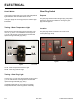
Start circuit (Fig. 0825) 2.0mm fusible link:
Fig 0825 PICT-5613a
When current ow in the circuit exceeds that of the
fusible link, the wire melts and interrupts the circuit.
How It Works
Testing
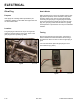
2.0mm fusible link:
Check for a failure of the 30 amp fuse rst. Check for
12 volts at the solenoid stud. Remove the heat shrink
from the splice. Use a test light to check for power at the
terminal end and of the splice. If power is present at one
end and not the other, then the fusible link is bad.
Testing the fusible link with an ohmmeter:
Attach the ohmmeter leads to each side of the link. If it
is good, you will get a reading on the meter. If not, it will
read open. A fusible link that has seen excessive current
will also have brittle or melted insulation.
.8mm fusible link:
Remove the heat shrink from the splice. Use a test light
to check for power at the starter solenoid terminal end
of the splice. If power is present at one end and not the
other, then the fusible link is bad.
Testing the fusible link with an ohmmeter:
Disconnect the wire from the starter solenoid. Attach the
ohmmeter leads to each side of the link. If it is good, you
will get a reading on the meter. If not, it will read open.
A fusible link that has seen excessive current will also
have brittle or melted insulation.