
Service Manual


HYDRAULIC SYSTEM
6-11TX525 Service Manual Rev. 000
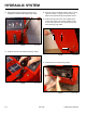
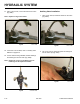
9. Using a 1-1/8” wrench, remove the hydraulic line
marked A from the auxiliary valve tting (Fig. 0869).
Fig 0869 PICT-4903a
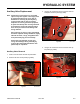
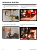
10. Using a 15/16” wrench, remove the hydraulic line
marked B from the auxiliary valve tting (Fig. 0870).
Fig 0870 PICT-4904a
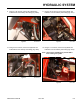
11. Using a 15/16” wrench, remove the hydraulic line
marked C from the auxiliary valve tting (Fig. 0871).
Fig 0871 PICT-4906
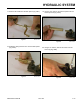
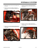
12. Using a 1-1/8” wrench, remove the hydraulic line
marked D from the auxiliary valve tting (Fig. 0872).
Note: Capalllinesandttingstopreventdebris
from entering the system.
Fig 0872 PICT-4909