
Service Manual


HYDRAULIC SYSTEM
6-22 Rev. 000 TX525 Service Manual
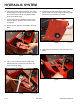
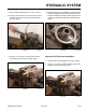
4. Using a 3/8” socket, remove the 3 self-tapping
screws that secure the top right panel to the control
panel assembly. Using a 3/8” socket and a 7/16”
socket, remove the bolt and nut securing the lower
left corner of the top right panel to the control panel
assembly (Fig. 0913).
Fig 0913 PICT-4341
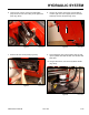
5. Remove the right panel from the control panel
assembly (Fig. 0914).
A. Self-tapping screw (3) B. Bolt and nut
Fig 0914 PICT-4343a
A
A
A
B
Fig 0912 PICT-4342
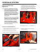
1. Raise the machine and set it on jack stands. Refer to
“Lifting the Machine for Service” on page 7-1.
2. Place the brake handle in the “OFF” position.
3. Remove the knob from the brake handle (Fig. 0912).
Hydraulic Oil Filter Head Removal
Hydraulic Oil Filter Head
Replacement
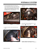
Note: Cleanliness is a key factor in a successful
repair of any hydraulic system. Thoroughly
clean all exposed surfaces prior to any type
of maintenance. Cleaning all parts by using
a solvent wash and air drying is usually
adequate. As with any precision equipment,
all parts must be kept free of foreign material
and chemicals. Protect all exposed sealing
areas and open cavities from damage and
foreign material.
Upon removal, all seals, o-rings, and gaskets
should be replaced. During installation, lightly
lubricate all seals, o-rings, and gaskets with
clean petroleum jelly prior to assembly.
Protect the inner diameter of seals and
o-rings from damage during assembly by
covering the shaft machined features with
plastic wrap or equivalent.