
Service Manual


HYDRAULIC SYSTEM
6-23TX525 Service Manual Rev. 000
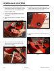
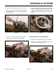
6. Using a 15/16” wrench, remove the hydrostatic
pump return line from the T-tting on the right hand
pump (Fig. 0915).
8. Using a 3/8” socket, remove the 3 screws that se-
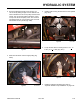
cure the right rear cover support panel to the tower
assembly. Remove the panel (Fig. 0917).
Fig 0915 PICT-4922
Fig 0917 PICT-4504
9. Place absorbent cloth over the battery area to soak
up the hydraulic uid that will drain from the lter and
lter head.
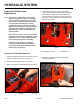
10. Using a lter wrench, remove the hydraulic oil lter
(Fig. 0918).
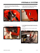
7. Remove the rear access panel (Fig. 0916).
Fig 0918 PICT-4918
Fig 0916 PICT-4505