
Service Manual


HYDRAULIC SYSTEM
6-96 Rev. 000 TX525 Service Manual
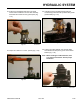
Lift Cylinder Disassembly
INSPECT TUBE ASSEMBLY: Visually inspect the
inside bore for scratches and pits. There should
be no scratches or pits deep enough to catch the
ngernail. Scratches that catch the ngernail but
are less than 0.5” long (1.27cm) and primarily in the
circumferential direction are acceptable provided
they cannot cut the piston seal. In the event that an
unacceptable condition occurs, the cylinder should
be replaced (Fig. 1196).
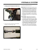
1. Remove the wear ring from the piston (Fig. 1197).
Fig 1196 PICT-3039a
Fig 1197 PICT-3040
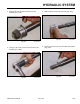
2. Remove the piston seal from the ram assembly (Fig.
1198).
Fig 1198 PICT-3041a
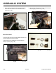
A. Barrel D. Head
B. Retaining Ring E. Ram
C. Piston
A
B
C D
E