
Operator's Manual


ReplacingtheTracks(Models22321
and22321G)
Whenthetracksarebadlyworn,replacethem.
1.Lowertheloaderarms,stoptheengine,andremove
thekey.
2.Lift/supportthesideoftheunittobeworkedonso
thatthetrackis3to4inches(7.6to10cm)offofthe
ground.
3.Removethelockingboltandnut(Figure41).
4.Usinga1/2inchdrivesocketwrench,releasethedrive
tensionbyturningthetensioningscrewclockwise
(Figure41andFigure42).
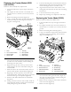
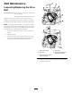
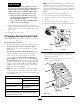
Figure42
1.Track5.Tracklug
2.1/2inchsocketwrench
6.Drivesprocket
3.Tensionwheel
7.Sprocketcog
4.Tensiontube8.Roadwheels
5.Pushthetensionwheeltowardtherearoftheunitto
movethetensiontubeagainsttheframe(
Figure42).
(Ifitdoesnottouchtheframe,continueturningthe
tensioningscrewuntilitdoes.)
6.Beginremovingthetrackatthetopofthetension
wheel,peelingitoffofthewheelwhilerotatingthe
trackforwards.
7.Whenthetrackisoffofthetensionwheel,removeit
fromthedrivesprocketandroadwheels(Figure42).
8.Beginningatthedrivesprocket,coilthenewtrack
aroundthesprocket,ensuringthatthelugsonthetrack
tbetweenthecogsonthesprocket(Figure42).
9.Pushthetrackunderandbetweentheroadwheels
(
Figure42).
10.Startingatthebottomofthetensionwheel,installthe
trackaroundthewheelbyrotatingthetrackrearward
whilepushingthelugsintothewheel.
11.Turnthetensioningscrewcounter-clockwiseuntilthe
distancebetweenthetensionnutandthebackofthe
tensiontube(Figure40)is2-3/4inches(7cm).
12.Aligntheclosestnotchinthetensionscrewtothe
lockingboltholeandsecurethescrewwiththelocking
boltandnut.
13.Lowerthetractionunittotheground.
14.Repeatsteps2through13toreplacetheothertrack.
ReplacingtheTracks(Model22322)
Whenthetracksarebadlyworn,replacethem.
1.Lowertheloaderarms,stoptheengine,andremove
thekey.
2.Lift/supportthesideoftheunittobeworkedonso
thatthetrackis3to4inches(7.6to10cm)offofthe
ground.
3.Removethelockingboltandnut(Figure41).
4.Usinga1/2inchdrivesocketwrench,releasethedrive
tensionbyturningthetensioningscrewclockwise
(Figure41andFigure43).
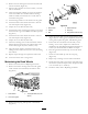
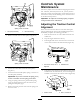
Figure43
1.Track6.Tracklug
2.1/2inchsocketwrench
7.Drivesprocket
3.Tensionwheelnut
8.Sprocketcog
4.Outertensionwheel
9.Roadwheels
5.Tensiontube10.Innertensionwheel
5.Pushthetensionwheeltowardtherearoftheunitto
movethetensiontubeagainsttheframe(Figure43).
(Ifitdoesnottouchtheframe,continueturningthe
tensioningscrewuntilitdoes.)
6.Removethenutsecuringtheoutertensionwheeland
removethewheel(
Figure43).
7.Removethetrack(Figure43).
33