Form No. 3360-384 Rev B TX 427 Compact Utility Loader Model No. 22321—Serial No. 280000001 and Up Model No. 22321G—Serial No. 280000001 and Up Model No. 22322—Serial No. 280000001 and Up To register your product or download an Operator's Manual or Parts Catalog at no charge, go to www.Toro.com.
Warning CALIFORNIA Proposition 65 Warning The engine exhaust from this product contains chemicals known to the State of California to cause cancer, birth defects, or other reproductive harm. Because in some areas there are local, state, or federal regulations requiring that a spark arrester be used on the engine of this machine, a spark arrester is available as an option. If you require a spark arrestor, contact your Authorized Service Dealer. Figure 1 1.
Contents Adjusting the Traction Control Alignment ...................................................... 36 Adjusting the Traction Control Neutral Position.......................................................... 37 Adjusting the Tracking of the Traction Control, Full Forward Position........................ 37 Hydraulic System Maintenance ............................... 38 Replacing the Hydraulic Filter ............................. 38 Changing the Hydraulic Fluid .............................
Safety • Inspect the area where the equipment is to be used and remove all objects such as rocks, toys, and wire which can be thrown by the machine. • Use extra care when handling gasoline and other fuels. They are flammable and vapors are explosive. – Use only an approved container – Never remove the gas cap or add fuel with the engine running. Allow the engine to cool before refueling. Do not smoke. – Never refuel or drain the machine indoors.
• Read all attachment manuals. • Ensure that the area is clear of other people before operating the traction unit. Stop the traction unit if anyone enters the area. • Never leave a running traction unit unattended. Always lower the loader arms, stop the engine, set the parking brake, and remove the key before leaving. • Do not exceed the rated operating capacity, as the traction unit may become unstable which may result in loss of control. • Do not carry a load with the arms raised.
– Keep container nozzle in contact with the tank during filling. • Let the engine cool before storing and do not store near flame. • Do not store fuel near flames or drain indoors. • Park the machine on level ground. Never allow untrained personnel to service the machine. • Use jack stands to support components when required. • Carefully release pressure from components with stored energy. • Disconnect the battery or remove the spark plug wires before making any repairs.
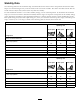
Stability Data The following tables list the maximum slope recommended for the traction unit in the positions listed in the tables. Slopes over the listed degree may cause the traction unit to become unstable. The data in the tables assume that the loader arms are fully lowered; raised arms may affect the stability. In each attachment manual is a set of three stability ratings, one for each hill position.
Slope Indicator 8
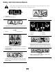
Safety and Instructional Decals Safety decals and instructions are easily visible to the operator and are located near any area of potential danger. Replace any decal that is damaged or lost. 93-6686 1. Hydraulic oil 2. Read the Operator’s Manual. 100-8822 1. Warning—do not carry passengers. 93-7814 1. Entanglement hazard, belt—stay away from moving parts. 93-9084 1. Lift point 115-4020 2. Tie-down point 1. Turn right 2. Forward 3. Reverse 4. Turn left 115-4855 1.
115-4861 1. Auxiliary hydraulics 2. Locked reverse (detent) 115-4857 1. Lower the loader arms. 2. Dump the bucket. 3. Forward 4. Neutral (off) 4. Curl the bucket. 5. Float the bucket on the ground. 3. Raise the loader arms. 115-4858 1. Crushing hazard of hands or feet—install the cylinder lock. 115-4862 1. Loader valve lock, unlocked 2. Loader valve lock, locked 115-4882 1. Warning—stay a safe distance from the hot surfaces. 115-4859 1. Disengaged 2. Parking brake 3.
107-9309 1. Warning—read the Operator’s Manual for information on charging the battery; contains lead; do not discard. 2. Read the Operator’s Manual. 115-4860 1. 2. 3. 4. Warning—read the Operator’s Manual. Warning—set the parking brake, stop the engine, remove the ignition key and lower the loader arms before leaving the machine. Crushing hazard—install the cylinder lock and read the instructions before servicing or performing maintenance.
Product Overview Figure 3 1. 2. 3. 4. Track Track adjustment chamber Lift cylinder Cylinder lock 5. 6. 7. 8. Loader arms 9. Mount plate Hood 10. Tie-down/lift loop Auxiliary hydraulic couplers 11. Control panel Tilt cylinder 12. Rear access cover 13. Fuel tank 14. Reverse safety plate Controls To stop the engine, rotate the key to the off position. Become familiar with all the controls (Figure 4) before you start the engine and operate the traction unit.
Traction Control G008131 Figure 8 Figure 5 • To turn left, rotate the traction control counterclockwise (Figure 9). 1. Reference bar (does not move to give you a reference point and a fixed handle to hold while operating the traction unit) 2. Traction control (moves to control the machine) • To move forward, move the traction control forward (Figure 6). G008132 Figure 9 • To stop, release the traction control (Figure 5).
To operate a hydraulic attachment in reverse direction, rotate the hydraulics lever rearward, then move it left into the upper slot (Figure 12, number 2). If you release the lever while in the forward position, the lever will automatically return to the neutral position (Figure 12, number 3). If it is in the reverse position, it will remain there until you pull it out of the slot. Figure 10 1. Lower the loader arms 2. Raise the loader arms 3. Tilt the attachment rearward 4. Tilt the attachment forward 5.
Hour Meter/Tachometer to remind you to change the engine oil. After every 100 hours, the screen displays SVC to remind you to perform the other maintenance procedures based on a 100, 200, or 400 hour schedule. These reminders come on starting three hours prior to the service interval time and flash at regular intervals for six hours. When the engine is off, the hour meter/tachometer displays the number of hours of operation that have been logged on the traction unit.
Operation In certain conditions during fueling, static electricity can be released causing a spark which can ignite the gasoline vapors. A fire or explosion from gasoline can burn you and others and can damage property. Note: Determine the left and right sides of the machine from the normal operating position. Important: Before operating, check the fuel and oil level, and remove debris from the traction unit. Also, ensure that the area is clear of people and debris.
chance of varnish deposits in the fuel system, use fuel stabilizer at all times. Filling the Fuel Tank 1. Park the traction unit on a level surface, lower the loader arms, and stop the engine. 2. Remove the key and allow the engine to cool. 3. Clean around the fuel tank cap and remove it. 4. Add unleaded gasoline to the fuel tank, until the level is just below the bottom of the filler neck. Figure 15 1. Filler cap Important: This space in the tank allows gasoline to expand.
lower), hydraulic system damage could occur. When starting the engine in cold conditions, allow the engine to run in the middle throttle position for 2 to 5 minutes before moving the throttle to fast (rabbit). Note: If outdoor temperature is below freezing, store the traction unit in a garage to keep it warmer and aid in starting. Stopping the Engine 1. Move the throttle lever to the slow (turtle) position. Figure 16 1. Filler neck cap 2. Lower the loader arms to the ground. 2. Dipstick 3.
1 3 G004182 2 Figure 18 1. Cylinder lock 2. Lift cylinder 3. Lynch pin Figure 17 1. Left tow valve (right track) 2. Right tow valve (left track) 5. Lower the cylinder lock over the cylinder rod and secure it with the lynch pin (Figure 18). 6. Slowly lower the loader arms until cylinder lock contacts the cylinder body and rod end. 4. Tow the traction unit as required. 5. When the traction unit has been repaired, close the tow valves before operating it.
warranty of the traction unit may be voided if used with unapproved attachments. Important: Before installing the attachment, ensure that the mount plates are free of any dirt or debris and that the pins rotate freely. If the pins do not rotate freely, grease them. 1. Position the attachment on a level surface with enough space behind it to accommodate the traction unit. 2. Start the engine. 3. Tilt the attachment mount plate forward. 4.
Important: Connect the attachment hoses together to prevent hydraulic system contamination during storage. 6. Push the attachment male connector into the female connector on the traction unit. Note: When you connect the attachment male connector first, you will relieve any pressure built up in the attachment. 6. Install the protective covers onto the hydraulic couplers on the traction unit. 7. Start the engine, tilt the mount plate forward, and back the traction unit away from the attachment.
Maintenance Note: Determine the left and right sides of the machine from the normal operating position. Recommended Maintenance Schedule(s) Maintenance Service Interval Maintenance Procedure After the first 8 hours • Replace the hydraulic filter. After the first 50 hours • Change the engine oil and filter. • Check and adjust the track tension. Before each use or daily Every 25 hours • • • • • • Check the engine oil level. Grease the traction unit. (Grease immediately after every washing.
If you leave the key in the ignition switch, someone could accidently start the engine and seriously injure you or other bystanders. Remove the key from the ignition and disconnect the wire from the spark plug before you do any maintenance. Set the wire aside so that it does not accidentally contact the spark plug. Premaintenance Procedures 1 Before opening any of the covers, stop the engine and remove the key. Allow the engine to cool before opening any covers 2 G006105 Figure 22 Opening the Hood 1.
Removing the Front Screen If the engine has been running the heat shield will be very hot and could burn you. Allow the traction unit cool completely before touching the heat shield. Figure 24 1. Open the hood and remove both side screens. 1. Hand knob 2. Loosen the bolts securing the front weight (Figure 26). 2. Tilt the rear access cover down and remove to access the internal components (Figure 24). Closing the Rear Access Cover 1.
Lubrication 6. Remove the shoulder bolts and nuts securing the oil cooler to the top of the front screen (Figure 28). Greasing the Traction Unit Service Interval: Before each use or daily (Grease immediately after every washing.) Grease Type: General-purpose grease. 1. Lower the loader arms and stop the engine. Remove the key. 2. Clean the grease fittings with a rag. 3. Connect a grease gun to each fitting (Figure 29). Figure 28 1. Nut 2. Oil cooler 3. Front screen 4. Shoulder bolts 7.
Engine Maintenance 8. Inspect the new filter(s) for damage by looking into the filter while shining a bright light on the outside of the filter. Holes in the filter will appear as bright spots. Inspect the element for tears, an oily film, or damage to the rubber seal. If the filter is damaged do not use it. Servicing the Air Cleaner Service Interval: Every 200 hours—Replace the primary air filter. Every 600 hours—Replace the safety air filter. 9.
Changing the Oil Changing the Oil Filter 1. Start the engine and let it run for five minutes. This warms the oil so it drains better. 1. Drain the oil from the engine; refer to Changing the Oil. 2. Place a shallow pan or rag under the filter to catch oil. 3. Remove the old filter (Figure 33) and wipe the surface of the filter adapter gasket. 2. Park the traction unit so that the drain side is slightly lower than the opposite side to ensure that the oil drains completely. 3.
3. Pull the wires off of the spark plugs (Figure 34). 3. Push the wires onto the spark plugs (Figure 34). 4. Close the hood. Figure 34 1. Spark plug wire 2. Spark plug 4. Clean around the spark plugs. 5. Remove both spark plugs and metal washers. Checking the Spark Plugs 1. Look at the center of both spark plugs (Figure 35). If you see light brown or gray on the insulator, the engine is operating properly. A black coating on the insulator usually means the air cleaner is dirty.
Draining the Fuel Tank Fuel System Maintenance In certain conditions, gasoline is extremely flammable and highly explosive. A fire or explosion from gasoline can burn you and others and can damage property. Changing the Fuel Filter Service Interval: Every 200 hours/Yearly (whichever comes first) • Drain gasoline from the fuel tank when the engine is cold. Do this outdoors in an open area. Wipe up any gasoline that spills. 1. Lower the loader arms, stop the engine, and remove the key. 2.
Electrical System Maintenance 2 Servicing the Battery 3 Service Interval: Every 100 hours—Check the battery electrolyte level (replacement battery only). 1 Every 100 hours—Check the battery cable connections. G003794 Figure 37 1. Filler caps 2. Upper line Warning CALIFORNIA Proposition 65 Warning Battery posts, terminals, and related accessories contain lead and lead compounds, chemicals known to the State of California to cause cancer and reproductive harm. Wash hands after handling. 3.
6. Install the battery filler caps. Drive System Maintenance Charging the Battery Servicing the Tracks level is up to the Upper line (Figure 37) on the battery case. Service Interval: After the first 50 hours—Check and adjust the track tension. Charging the battery produces gasses that can explode. Before each use or daily—Clean the tracks. Never smoke near the battery and keep sparks and flames away from battery.
Figure 41 Figure 39 1. Track 2. Drive sprocket 1. Locking bolt 2. Tensioning screw 3. Road wheels 4. Tension wheel 3. Tension tube 4. Tension wheel 4. Using a 1/2 inch drive socket wrench (Figure 42), turn the tensioning screw counter-clockwise until the distance between the tension nut and the back of the tension tube (Figure 40) is 2-3/4 inches (7 cm). Adjusting the Track Tension There should be 2-3/4 inches (7 cm) between the tension nut and the back of the tension tube (Figure 40).
Replacing the Tracks (Model 22322) When the tracks are badly worn, replace them. 1. Lower the loader arms, stop the engine, and remove the key. 2. Lift/support the side of the unit to be worked on so that the track is 3 to 4 inches (7.6 to 10 cm) off of the ground. 3. Remove the locking bolt and nut (Figure 41). 4. Using a 1/2 inch drive socket wrench, release the drive tension by turning the tensioning screw clockwise (Figure 41 and Figure 43). Figure 42 1. 2. 3. 4.
inside the wheels, then fill this area on each side of each wheel with grease. 11. Install the large washers on the wheels over the grease. 12. Install the inner tension wheel and secure it with the nut removed previously (Figure 43). 13. Torque the nut to 300 ft-lb (407 N-m). 14. Install the new track, ensuring that the lugs in the track fit between the cogs in the middle of the drive sprocket (Figure 43). Figure 45 15.
Belt Maintenance Inspecting/Replacing the Drive Belt Service Interval: Every 25 hours—Inspect the drive belt for wear or damage. Every 200 hours—Replace the drive belt. Replace the belt if you find any signs of wear, cracks, or damage or after 200 operating hours, whichever comes first.
Controls System Maintenance The factory adjusts the controls before shipping the traction unit. However, after many hours of use, you may need to adjust the traction control alignment, the neutral position of the traction control, and the tracking of the traction control in the full forward position. Important: To adjust the controls properly, complete each procedure in the order listed. Adjusting the Traction Control Alignment Figure 47 1. Idler pulley assembly 2.
Figure 50 1. Traction control 2. Stem , bolt and nut Figure 52 5. Adjust the traction control so that it rests flush against the reference bar when it is pulled straight back (Figure 50 and Figure 51). 1. Traction rod 2. Jam nut 4. Start the traction unit and set the throttle to about 1/3 open position. When the traction unit is running, you could be caught and injured in moving parts or burned on hot surfaces.
Hydraulic System Maintenance 1. Drive the traction unit with the traction control against the reference bar, noting which direction the traction unit veers. 2. Release the traction control. 3. If the traction unit veers to the left, loosen the right jam nut and adjust the tracking set screw on the front of the traction control (Figure 53). Replacing the Hydraulic Filter 4.
Hydraulic fluid escaping under pressure can penetrate skin and cause injury. Fluid injected into the skin must be surgically removed within a few hours by a doctor familiar with this form of injury or gangrene may result. • Keep your body and hands away from pin hole leaks or nozzles that eject high pressure hydraulic fluid. • Use cardboard or paper to find hydraulic leaks, never use your hands. Figure 55 1. Filler neck cap 11.
Cleaning 11. Stop the engine. 12. Check the hydraulic fluid level and top it off if necessary; refer to Checking Hydraulic Fluid. 13. Close the hood. Removing Debris from the Traction Unit Checking the Hydraulic Lines Service Interval: Before each use or daily Service Interval: Every 100 hours—Check the hydraulic lines for leaks, loose fittings, kinked lines, loose mounting supports, wear, weather, and chemical deterioration. (Make necessary repairs before operating.
Cleaning the Chassis Service Interval: Every 100 hours—Check for dirt build-up in the chassis. Over time, the chassis under the engine collects dirt and debris that must be removed. Using a flashlight, open the hood and inspect the area under the engine on a regular basis. When the debris is 1 to 2 inches deep, complete the following procedure (refer to Figure 57 throughout this procedure): Figure 58 1. Black wire 2. Orange wire 13.
22. Secure the battery tray with the bolts and washers removed previously. Storage 23. Install the side weights with the bolts, washers, and lock washers removed previously (Figure 57). 1. Lower the loader arms, stop the engine, and remove the key. 2. Remove dirt and grime from the external parts of the entire traction unit, especially the engine. Clean dirt and chaff from the outside of the engine cylinder head fins and blower housing. 24. Close the rear access cover. 25.
F. Start and run the engine until it will not start again. G. Dispose of fuel properly. Recycle as per local codes. Important: Do not store stabilizer/conditioned gasoline over 90 days. 13. Check and adjust the track tension; refer to Adjusting the Track Tension. 14. Check and tighten all bolts, nuts, and screws. Repair or replace any part that is damaged. 15. Paint all scratched or bare metal surfaces. Paint is available from your Authorized Service Dealer. 16.
Troubleshooting Problem The starter does not crank The engine will not start, starts hard, or fails to keep running. Engine loses power. The engine overheats. Possible Cause Corrective Action 1. The battery is discharged. 1. Charge the battery or replace it. 2. The electrical connections are corroded or loose. 3. The relay or switch is damaged. 2. Check the electrical connections for good contact. 3. Contact your Authorized Service Dealer. 1. The fuel tank is empty. 1.
Schematics Electrical Schematic (Rev.
Hydraulic Schematic (Rev.
Notes: 47
Toro Compact Utility Equipment Warranty CUE Products A One-Year Limited Warranty Conditions and Products Covered The Toro® Company and its affiliate, Toro Warranty Company, pursuant to an agreement between them, jointly warrant your Toro Compact Utility Equipment (“Product”) to be free from defects in materials or workmanship.