
Operator's Manual
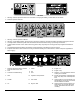
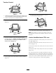
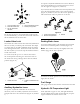
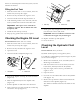
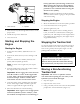
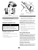


Figure17
1.Lefttowvalve(righttrack)2.Righttowvalve(lefttrack)
4.Towthetractionunitasrequired.
5.Whenthetractionunithasbeenrepaired,closethe
towvalvesbeforeoperatingit.
UsingtheCylinderLock
Theloaderarmsmaylowerwhenintheraised
positioncrushinganyoneunderthem.
Installthecylinderlockbeforeperforming
maintenancethatrequiresraisedloaderarms.
InstallingtheCylinderLock
1.Removetheattachment.
2.Raisetheloaderarmstothefullyraisedposition.
3.Stoptheengine.
4.Removethelynchpinsecuringthecylinderlockto
theloaderarm(Figure18).
G004182
3
2
1
Figure18
1.Cylinderlock
3.Lynchpin
2.Liftcylinder
5.Lowerthecylinderlockoverthecylinderrodand
secureitwiththelynchpin(Figure18).
6.Slowlylowertheloaderarmsuntilcylinderlock
contactsthecylinderbodyandrodend.
Removing/StoringtheCylinderLock
Important:Ensurethatthecylinderlockis
removedfromtherodandfullysecuredinthe
storagepositionbeforeoperatingthetractionunit.
1.Starttheengine.
2.Raisetheloaderarmstothefullyraisedposition.
3.Stoptheengine.
4.Removethelynchpinsecuringthecylinderlock.
5.Rotatethecylinderlockuptotheloaderarmand
secureitwiththelynchpin.
6.Lowertheloaderarms.
UsingAttachments
Important:Ifyouareusinganattachmentwitha
serialnumberof200999999orearlier,themanual
fortheattachmentmaycontaininformation
specictotheuseoftheattachmentwithother
tractionunitmodels,suchassettingsfortheow
dividercontrolandspeedselectorleverandthe
useofacounterweightonthetractionunit.These
systemsarebuiltintotheTX,andyoushould
ignoreanyreferencestothem.
InstallinganAttachment
Important:UseonlyToro-approvedattachments.
Attachmentscanchangethestabilityandthe
operatingcharacteristicsofthetractionunit.The
19