
Operator's Manual
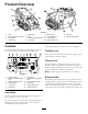
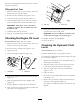
ProductOverview
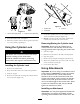
Figure3
1.Track5.Loaderarms9.Mountplate13.Fueltank
2.Trackadjustmentchamber6.Hood
10.Tie-down/liftloop14.Reversesafetyplate
3.Liftcylinder
7.Auxiliaryhydrauliccouplers
11.Controlpanel
4.Cylinderlock
8.Tiltcylinder12.Rearaccesscover
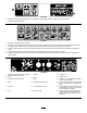
Controls
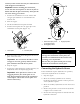
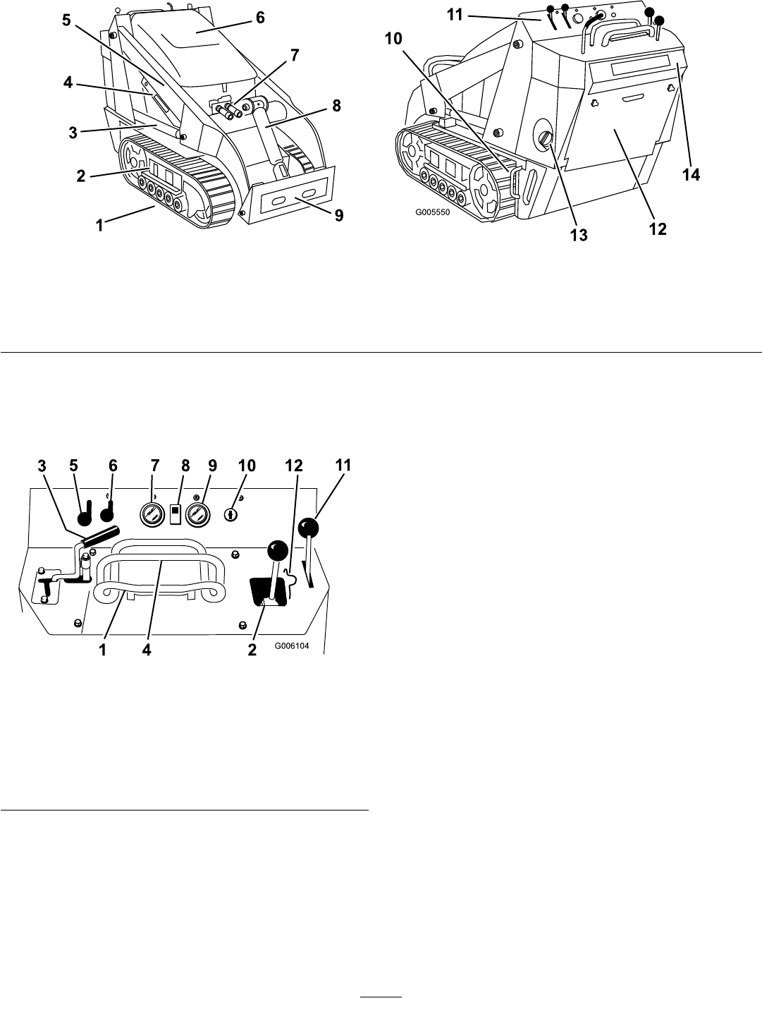
Becomefamiliarwithallthecontrols(Figure4)before
youstarttheengineandoperatethetractionunit.
G006104
3
5
6
7
8 9 1012
11
41 2
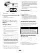
Figure4
1.Tractioncontrol7.Fuelgauge
2.Loaderarm/attachmenttilt
lever
8.Hydraulicoiltemperature
light
3.Auxiliaryhydraulicslever
9.Hourmeter/tachometer
4.Referencebar
10.Keyswitch
5.Throttlelever11.Parkingbrakelever
6.Chokelever
12.Loadervalvelock
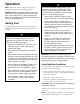
KeySwitch
Thekeyswitch,usedtostartandstoptheengine,has
threepositions:off,run,andstart.
Tostarttheengine,rotatethekeytothestartposition.
Releasethekeywhenenginestartsanditwillmove
automaticallytotherunposition.
Tostoptheengine,rotatethekeytotheoffposition.
ThrottleLever
Movethecontrolforwardtoincreasetheenginespeed
andrearwardtodecreasespeed.
ChokeLever
Beforestartingacoldengine,movethechokelever
forward.Aftertheenginestarts,regulatethechoketo
keeptheenginerunningsmoothly.Assoonaspossible,
movethechokeleverallthewayrearward.
Note:Awarmenginerequireslittleornochoking.
ReferenceBar
Whendrivingthetractionunit,usethereferencebaras
ahandleandaleveragepointforcontrollingthetraction
controlandtheauxiliaryhydraulicslever.Toensure
smooth,controlledoperation,donottakebothhands
offofthereferencebarwhileoperatingthetractionunit.
12