
Service Manual


8
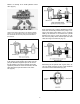
3. Lines
Figure 4
A hydraulic line, tube, hose or any conductor that
carries the liquid between components is shown as
a line. Some lines have arrows to show direction of
oil flow, and lines may be shown as dashed lines to
show certain types of oil flow.
Figure 5
There are lines that cross other lines (Fig 5) but are
not connected, there are several ways to show lines
that are not connected. Lines that are connected
are shown with a dot or sometime just as two lines
crossing. If the schematic shows a specific symbol
to show lines that are not connected then anything
else is connected.
4. Hydraulic pumps
Figure 6
There are many basic pump designs. (Fig 6) A sim-
ple fixed displacement pump is shown as a circle
with a triangle that is pointing outward. The triangle
points in the direction that the oil will flow. If the
pump is reversible or is designed to pump in either
direction, it will have two triangles in it and they will
point opposite of each other indicating that oil may
flow in both directions.
5. Hydraulic motors
Figure 7
Hydraulic motor symbols (Fig 7) are circles with tri-
angles, but opposite of a hydraulic pump, the tri-
angle points inward to show the oil flows in to the
motor. One triangle is used for a non-reversible
motor and two triangles are used for a reversible
motor. An arrow through a motor shows that it is a
variable speed motor.
6. Check valves
Figure 8
A check valve (Fig 8) is shown as a ball in a V
seat. When oil pressure is applied to the left side of
the ball, the ball is forced into the V and no oil can
flow. When oil pressure is applied to the right side
of the ball, the ball moves away from the seat and
oil can flow past it. A by-pass check is a one way
valve with a spring on the ball end of the symbol.
This shows that pressurized oil must overcome the
spring pressure before the ball will unseat.
7. Relief valves
Figure 9
A relief valve (Fig 9) is shown as a normally closed
valve with one port connected to the pressure line
and the other line connected to the reservoir. The
flow direction arrow points away from the pressure
line and toward the reservoir. When pressure in the
system overcomes the valve spring, pressure is di-
rected through the valve to the reservoir.
LINES