Form No. 3372-637 Rev B TX 427 Compact Utility Loader Model No. 22321—Serial No. 312000001 and Up Model No. 22321G—Serial No. 312000001 and Up Model No. 22322—Serial No. 312000001 and Up To register your product or download an Operator's Manual or Parts Catalog at no charge, go to www.Toro.com.
Introduction This product complies with all relevant European directives, for details please see the separate product specific Declaration of Conformity (DOC) sheet. This machine is a compact utility loader intended for use in various earth and materials moving activities for landscaping and construction work. It is designed to operate a wide variety of attachments each of which perform a specialized function.
Adjusting the Traction Control Neutral Position .............................................................37 Adjusting the Tracking of the Traction Control, Full Forward Position ..........................................37 Hydraulic System Maintenance ....................................38 Replacing the Hydraulic Filter ..................................38 Changing the Hydraulic Fluid...................................39 Checking the Hydraulic Lines...................................40 Cleaning ........
Safety • Improper use or maintenance by the operator or owner can result in injury. To reduce the potential for injury, comply with these safety instructions and always pay attention to the safety alert symbol , which means: Caution, Warning, or Danger—personal safety instruction. Failure to comply with the instruction may result in personal injury or death. Operation • Never run an engine in an enclosed area.
• Do not over-load the attachment and always keep the • • • • • • • • • terrain could overturn the traction unit. Tall grass can hide obstacles. load level when raising the loader arms. Logs, boards, and other items could roll down the loader arms, injuring you. Never jerk the controls; use a steady motion. Watch for traffic when operating near or crossing roadways. Do not touch parts which may be hot from operation. Allow them to cool before attempting to maintain, adjust, or service.
• Secure the loader arm valve with the loader valve lock The sound power level was determined according to the procedures outlined in ISO 6395. anytime you need to stop the machine with the loader arms raised. • Keep nuts and bolts tight. Keep equipment in good Vibration Level condition. Measured vibration level for right hand = 1.1 m/s2 • Never tamper with safety devices. • Keep the traction unit free of grass, leaves, or other debris Measured vibration level for left hand = 1.1 m/s2 build-up.
Stability Data The following tables list the maximum slope recommended for the traction unit in the positions listed in the tables. Slopes over the listed degree may cause the traction unit to become unstable. The data in the tables assume that the loader arms are fully lowered; raised arms may affect the stability. In each attachment manual is a set of three stability ratings, one for each hill position.
Slope Indicator G011841 Figure 3 This page may be copied for personal use. 1. To determine the maximum slope you can safely operate the machine on, refer to the Stability Data section. Use the slope indicator to determine the degree of slope of hills before operating. Do not operate this machine on a slope greater than that specified in the Stability Data section. Fold along the appropriate line to match the recommended slope. 2. Align this edge with a vertical surface, a tree, building, fence pole, etc.
Safety and Instructional Decals Safety decals and instructions are easily visible to the operator and are located near any area of potential danger. Replace any decal that is damaged or lost. 100-8821 93-6686 1. Crushing hazard and cutting hazard of hand—stay a safe distance from the front of the traction unit when the loader arms are raised. 1. Hydraulic oil 2. Read the Operator's Manual. 93-7814 1. Entanglement hazard, belt—stay away from moving parts. 100-8822 1. Warning—do not carry passengers.
115-4856 1. Warning—read the Operator's Manual; maximum load rating of 500 lb (228 Kg); no riders. 115-4861 1. Auxiliary hydraulics 3. Forward 2. Locked reverse (detent) 4. Neutral (off) 115-4857 1. Lower the loader arms. 2. Dump the bucket. 4. Curl the bucket. 5. Float the bucket on the ground. 115-4862 3. Raise the loader arms. 1. Loader valve lock, unlocked 2. Loader valve lock, locked 115-4858 1. Crushing hazard of hands or feet—install the cylinder lock. 115-4882 1.
7–1806 115-4860 1. Warning—read the Operator's Manual. 2. Warning—set the parking brake, stop the engine, remove the ignition key and lower the loader arms before leaving the machine. 3. Crushing hazard—install the cylinder lock and read the instructions before servicing or performing maintenance. 4. Cutting hazard of hands or feet—wait for all moving parts to stop; stay away from moving parts; keep all guards and shields in place. 5.
117-4045 1. Read the Operator's Manual, located inside the rear access cover. 2. Fast 7. Choke 13. Engine—run 8. Off 14. Engine—stop 3. Continuous variable setting 9. Fuel 15. Warning— do not operate this machine unless you are trained. 4. Slow 10. Hydraulic oil temperature 5. Throttle 11. Hour meter 6. On 12. Engine—start 12 16. Electric shock hazard, overhead power lines—stay away from overhead power lines. 17.
Product Overview Figure 4 1. Track 5. Loader arms 2. Track adjustment chamber 6. Hood 9. Mount plate 10. Tie-down/lift loop 3. Lift cylinder 7. Auxiliary hydraulic couplers 11. Control panel 4. Cylinder lock 8. Tilt cylinder 13. Fuel tank 14. Reverse safety plate 12. Rear access cover Controls To start the engine, rotate the key to the start position. Release the key when engine starts and it will move automatically to the run position.
Traction Control G008131 Figure 9 Figure 6 • To turn left, rotate the traction control counterclockwise (Figure 10). 1. Reference bar (does not move to give you a reference point and a fixed handle to hold while operating the traction unit) 2. Traction control (moves to control the machine) • To move forward, move the traction control forward (Figure 7). G008132 Figure 10 • To stop, release the traction control (Figure 6).
Auxiliary Hydraulics Lever To operate a hydraulic attachment in the forward direction, rotate the auxiliary hydraulics lever rearward and pull it down to the reference bar (Figure 13, number 1). To operate a hydraulic attachment in reverse direction, rotate the hydraulics lever rearward, then move it left into the upper slot (Figure 13, number 2). If you release the lever while in the forward position, the lever will automatically return to the neutral position (Figure 13, number 3).
Hydraulic Oil Temperature Light After 50 hours and then every 100 hours thereafter (that is at 150, 250, 350, etc.) the screen displays CHG OIL to remind you to change the engine oil. After every 100 hours, the screen displays SVC to remind you to perform the other maintenance procedures based on a 100, 200, or 400 hour schedule. These reminders come on starting three hours prior to the service interval time and flash at regular intervals for six hours.
Operation DANGER In certain conditions during fueling, static electricity can be released causing a spark which can ignite the gasoline vapors. A fire or explosion from gasoline can burn you and others and can damage property. Note: Determine the left and right sides of the machine from the normal operating position. Important: Before operating, check the fuel and oil level, and remove debris from the traction unit. Also, ensure that the area is clear of people and debris.
Note: The cap is tethered to the fuel tank. Important: Do not overfill the crankcase with oil because the engine may be damaged. 4. Add unleaded gasoline to the fuel tank, until the level is just below the bottom of the filler neck. 10. Replace the filler cap and dipstick. Important: This space in the tank allows gasoline to expand. Do not fill the fuel tank completely full. 11. Close the hood. 5. Install the fuel tank cap securely, turning it until it clicks. Checking the Hydraulic Fluid Level 6.
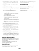
Starting and Stopping the Engine Stopping the Traction Unit To stop the traction unit, release the traction control, move the throttle lever to slow (turtle), lower loader arms to the ground, and stop the engine. Set the parking brake and remove the key. Starting the Engine 1. Ensure that the auxiliary hydraulics lever is in neutral. CAUTION 2. Move the choke lever forward to the On position if you are starting a cold engine.
Using Attachments Using the Cylinder Lock Important: If you are using an attachment with a serial number of 200999999 or earlier, the manual for the attachment may contain information specific to the use of the attachment with other traction unit models, such as settings for the flow divider control and speed selector lever and the use of a counterweight on the traction unit. These systems are built into the TX, and you should ignore any references to them.
aligned with the holes in the attachment receiver plate. Check the receiver plate and clean it if necessary. 6. Push the attachment male connector into the female connector on the traction unit. Note: When you connect the attachment male connector first, you will relieve any pressure built up in the attachment. WARNING Hydraulic fluid escaping under pressure can penetrate skin and cause injury.
6. Install the protective covers onto the hydraulic couplers on the traction unit. 7. Start the engine, tilt the mount plate forward, and back the traction unit away from the attachment. Securing the Traction Unit for Transport When transporting the traction unit on a trailer, always use the following procedure: Important: Do not operate or drive the traction unit on roadways. 1. Lower the loader arms. 2. Stop the engine. 3.
Maintenance Note: Determine the left and right sides of the machine from the normal operating position. Recommended Maintenance Schedule(s) Maintenance Service Interval Maintenance Procedure After the first 8 hours • Replace the hydraulic filter. After the first 50 hours • Change the engine oil and filter. • Check and adjust the track tension. Before each use or daily Every 25 hours • • • • • • • Check the engine oil level. Grease the traction unit. (Grease immediately after every washing.
Premaintenance Procedures Before opening any of the covers, stop the engine and remove the key. Allow the engine to cool before opening any covers Important: If you will be tilting the machine more than 25 degrees, clamp off the vent hose on the top of the fuel tank (Figure 58) to prevent fuel from fouling the carbon canister. Figure 23 Opening the Hood 1. Loosen the hood locking screw (Figure 22) 1. Prop rod 3. Hood 2. Bracket 4. Prop rod holder Closing the Hood 1.
Removing the Side Screens 3. Remove the carriage bolts and nuts securing the sloped plate (Figure 26). 1. Open the hood. 2. Slide the side screens (Figure 25) up and out of the slots in the front screen and frame. 4. Lift the sloped plate up and off of the traction unit. 5. Remove the 4 bolts securing the front screen to the traction unit frame (Figure 27). Figure 25 1. Side screen Figure 27 Installing the Side Screens 1. Front screen 2.
Lubrication Engine Maintenance Greasing the Traction Unit Servicing the Air Cleaner Service Interval: Before each use or daily (Grease immediately after every washing.) Service Interval: Before each use or daily—Check the air filter service indicator. Every 25 hours—Remove air cleaner cover, clean out debris, and check the air filter service indicator. Every 600 hours—Replace the safety air filter. Grease Type: General-purpose grease. 1. Lower the loader arms and stop the engine. Remove the key. 2.
Servicing the Engine Oil • If the service indicator is clear, clean any debris from cover and install cover. Service Interval: After the first 50 hours Ensure that the cover is seated correctly and seals with the air cleaner body. Every 100 hours—Change the engine oil. Every 200 hours—Change the oil filter. • If the service indicator is red, replace the air filter as described in Replacing the Filters. Note: Change oil and filter more frequently when operating conditions are extremely dusty or sandy.
Changing the Oil Filter 1. Drain the oil from the engine; refer to Changing the Oil (page 27). 2. Place a shallow pan or rag under the filter to catch oil. 3. Remove the old filter (Figure 33) and wipe the surface of the filter adapter gasket. Figure 32 1. Oil drain valve 5. When the oil has drained completely, replace the plug. Note: Dispose of the used oil at a certified recycling center. 6.
Fuel System Maintenance Changing the Fuel Filter Service Interval: Every 200 hours/Yearly (whichever comes first) 1. Lower the loader arms, stop the engine, and remove the key. Figure 34 1. Spark plug wire 2. Open the hood and remove the left side screen. 2. Spark plug 3. Loosen the tank cap to relieve pressure. 4. Clamp the fuel lines on both sides of the fuel filter (Figure 36). 4. Clean around the spark plugs. 5. Remove both spark plugs and metal washers. Checking the Spark Plugs 1.
Draining the Fuel Tank Electrical System Maintenance DANGER In certain conditions, gasoline is extremely flammable and highly explosive. A fire or explosion from gasoline can burn you and others and can damage property. Servicing the Battery Service Interval: Every 100 hours—Check the battery electrolyte level (replacement battery only). • Drain gasoline from the fuel tank when the engine is cold. Do this outdoors in an open area. Wipe up any gasoline that spills.
level is up to the Upper line (Figure 37) on the battery case. 6. Install the battery filler caps. 2 Charging the Battery 3 WARNING Charging the battery produces gasses that can explode. 1 G003794 Never smoke near the battery and keep sparks and flames away from battery. Figure 37 1. Filler caps 3. Lower line Important: Always keep the battery fully charged (1.265 specific gravity). This is especially important to prevent battery damage when the temperature is below 32°F (0°C). 2. Upper line 4.
Adjusting the Track Tension Drive System Maintenance There should be 2-3/4 inches (7 cm) between the tension nut and the back of the tension tube (Figure 40). If not, adjust the track tension using the following procedure: Servicing the Tracks Service Interval: After the first 50 hours—Check and adjust the track tension. Before each use or daily—Clean the tracks. Before each use or daily—Check the tracks for excessive wear (If the tracks are worn, replace them.
Replacing the Tracks (Models 22321 and 22321G) 11. Turn the tensioning screw counter-clockwise until the distance between the tension nut and the back of the tension tube (Figure 40) is 2-3/4 inches (7 cm). When the tracks are badly worn, replace them. 1. Lower the loader arms, stop the engine, and remove the key. 2. Lift/support the side of the unit to be worked on so that the track is 3 to 4 inches (7.6 to 10 cm) off of the ground. 3. Remove the locking bolt and nut (Figure 41). 4.
8. Remove the nut securing the inner tension wheel and remove the wheel (Figure 43). 9. Pull the 4 large washers out of the 2 wheels, 1 on each side of each wheel. 10. Clean the old grease and dirt out of the area between where the washers were installed and the bearings inside the wheels, then fill this area on each side of each wheel with grease. 11. Install the large washers on the wheels over the grease. 12. Install the inner tension wheel and secure it with the nut removed previously (Figure 43).
Belt Maintenance Inspecting/Replacing the Drive Belt Service Interval: Every 25 hours—Inspect the drive belt for wear or damage. Every 200 hours—Replace the drive belt. Replace the belt if you find any signs of wear, cracks, or damage or after 200 operating hours, whichever comes first.
Controls System Maintenance The factory adjusts the controls before shipping the traction unit. However, after many hours of use, you may need to adjust the traction control alignment, the neutral position of the traction control, and the tracking of the traction control in the full forward position. Important: To adjust the controls properly, complete each procedure in the order listed. Adjusting the Traction Control Alignment Figure 47 Spring cover not shown 1.
5. Adjust the traction control so that it rests flush against the reference bar when it is pulled straight back (Figure 50 and Figure 51). WARNING When the traction unit is running, you could be caught and injured in moving parts or burned on hot surfaces. Stay away from pinch points, moving parts, and hot surfaces when adjusting the running traction unit. 5. If the left track moves, lengthen or shorten the right traction rod until the track stops moving. Figure 51 6.
Hydraulic System Maintenance Replacing the Hydraulic Filter Service Interval: After the first 8 hours Every 200 hours Important: Do not substitute an automotive oil filter or severe hydraulic system damage may result. 1. Position traction unit on a level surface. Figure 53 1. Set screw 2. Lower the loader arms, stop the engine, and remove the key. 3. Stop 2. Jam nut 3. Open the rear access cover. 4. Place a drain pan under the filter (Figure 54). 5.
Note: Many hydraulic fluids are almost colorless, making it difficult to spot leaks. A red dye additive for the hydraulic system oil is available in 2/3 oz (20 ml) bottles. One bottle is sufficient for 4-6 gal (15-22 l) of hydraulic oil. Order part no. 44-2500 from your Authorized Toro Dealer. WARNING Hydraulic fluid escaping under pressure can penetrate skin and cause injury.
Checking the Hydraulic Lines 7. Remove the drain plug and allow the oil to drain into the pan (Figure 56). Service Interval: Every 100 hours—Check the hydraulic lines for leaks, loose fittings, kinked lines, loose mounting supports, wear, weather, and chemical deterioration. (Make necessary repairs before operating.) 8. When finished, install and tighten the drain plug. Note: Dispose of the used oil at a certified recycling center. 9. Fill the hydraulic tank with approximately 12 US gallons (45.
Cleaning the Chassis Cleaning Service Interval: Every 100 hours—Check for dirt build-up in the chassis. Removing Debris from the Traction Unit Over time, the chassis under the engine collects dirt and debris that must be removed. Using a flashlight, open the hood and inspect the area under the engine on a regular basis.
16. Slide the fuel tank part way into the chassis (Figure 57). 17. Remove the plug from the vent fitting and connect the vent hose to it. 18. Connect the fuel line and remove the clamp. 19. Secure the tank cap and tighten it until it clicks. 20. On the right side of the tank, connect the orange wire to the center post and the black wire to the outside post (Figure 58). 21. Slide the tank all the way into the traction unit.
Storage Important: Do not store stabilizer/conditioned gasoline over 90 days. 1. Lower the loader arms, stop the engine, and remove the key. 12. Check and adjust the track tension; refer to Adjusting the Track Tension (page 32). 2. Remove dirt and grime from the external parts of the entire traction unit, especially the engine. Clean dirt and chaff from the outside of the engine cylinder head fins and blower housing. 13. Check and tighten all bolts, nuts, and screws.
Troubleshooting Problem The starter does not crank The engine will not start, starts hard, or fails to keep running. Engine loses power. The engine overheats. Possible Cause Corrective Action 1. The battery is discharged. 1. Charge the battery or replace it. 2. The electrical connections are corroded or loose. 3. The relay or switch is damaged. 2. Check the electrical connections for good contact. 3. Contact your Authorized Service Dealer. 1. The fuel tank is empty. 1.
Schematics g013124 Electrical Schematic (Rev.
Hydraulic Schematic (Rev.
Notes: 47
Toro Compact Utility Equipment Warranty A One-Year Limited Warranty Conditions and Products Covered The Toro® Company and its affiliate, Toro Warranty Company, pursuant to an agreement between them, jointly warrant your Toro Compact Utility Equipment (“Product”) to be free from defects in materials or workmanship.