
Operator's Manual


ProductOverview
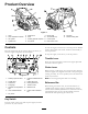
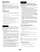
Figure4
1.Track5.Loaderarms9.Mountplate13.Fueltank
2.Trackadjustmentchamber6.Hood
10.Tie-down/liftloop14.Reversesafetyplate
3.Liftcylinder
7.Auxiliaryhydrauliccouplers
11.Controlpanel
4.Cylinderlock
8.Tiltcylinder12.Rearaccesscover
Controls
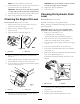
Becomefamiliarwithallthecontrols(Figure5)beforeyou
starttheengineandoperatethetractionunit.
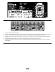
Figure5
1.Auxiliaryhydraulicslever
8.Loaderarm/attachmenttilt
lever
2.Throttlelever9.Loadervalvelock
3.Chokelever
10.Parkingbrakelever
4.Fuelgauge11.Tractioncontrol
5.Hydraulicoiltemperature
light
12.Referencebar
6.Hourmeter/tachometer13.Loadercontrolreference
bar
7.Keyswitch
KeySwitch
Thekeyswitch,usedtostartandstoptheengine,hasthree
positions:off,run,andstart.
Tostarttheengine,rotatethekeytothestartposition.Release
thekeywhenenginestartsanditwillmoveautomaticallyto
therunposition.
Tostoptheengine,rotatethekeytotheoffposition.
ThrottleLever
Movethecontrolforwardtoincreasetheenginespeedand
rearwardtodecreasespeed.
ChokeLever
Beforestartingacoldengine,movethechokeleverforward.
Aftertheenginestarts,regulatethechoketokeeptheengine
runningsmoothly.Assoonaspossible,movethechokelever
allthewayrearward.
Note:Awarmenginerequireslittleornochoking.
ReferenceBar
Whendrivingthetractionunit,usethereferencebaras
ahandleandaleveragepointforcontrollingthetraction
controlandtheauxiliaryhydraulicslever.Toensuresmooth,
controlledoperation,donottakebothhandsoffofthe
referencebarwhileoperatingthetractionunit.
13