Form No. 3420-641 Rev A TX 525 Compact Tool Carrier Model No. 22323—Serial No. 401800000 and Up Model No. 22323G—Serial No. 401800000 and Up Model No. 22324—Serial No. 401800000 and Up Register at www.Toro.com.
Introduction This product complies with all relevant European directives; for details, please see the separate product specific Declaration of Conformity (DOC) sheet. This machine is a compact tool carrier intended for use in various earth and materials moving activities for landscaping and construction work. It is designed to operate a wide variety of attachments each of which perform a specialized function.
Bleeding the Fuel System ................................. 29 Draining the Fuel Tank(s).................................. 30 Electrical System Maintenance ........................... 30 Electrical System Safety ................................... 30 Servicing the Battery......................................... 31 Servicing the Fuses .......................................... 33 Drive System Maintenance .................................. 34 Servicing the Tracks .........................................
Safety General Safety Always follow all safety instructions to avoid serious injury or death. Using this product for purposes other than its intended use could prove dangerous to you and bystanders. • Do not carry a load with the arms raised; always carry loads close to the ground. • Slopes are a major factor related to loss-of-control and tip-over accidents, which can result in severe injury or death. Operating the machine on any slope or uneven terrain requires extra caution.
Safety and Instructional Decals Safety decals and instructions are easily visible to the operator and are located near any area of potential danger. Replace any decal that is damaged or missing. decal93-7814 93-7814 1. Entanglement hazard, belt—stay away from moving parts. decalbatterysymbols Battery Symbols Some or all of these symbols are on your battery. 1. Explosion hazard 6. Keep bystanders a safe distance from the battery. 2. No fire, open flame, or smoking 7.
decal100-8822 100-8822 1. Warning—do not carry passengers. decal115-4857 115-4857 1. Lower the loader arms. 2. Dump the bucket. 4. Curl the bucket. 5. Float the bucket on the ground. 3. Raise the loader arms. decal106-6755 106-6755 1. Engine coolant under pressure. 3. Warning—do not touch the hot surface. 2. Explosion hazard—read the Operator's Manual. 4. Warning—read the Operator's Manual. decal115-4858 115-4858 1. Crushing hazard of hands or feet—install the cylinder lock.
decal115-4865 115-4865 1. Engine coolant 2. Read the Operator's Manual. decal115-4861 115-4861 1. Auxiliary hydraulics 3. Forward 2. Locked reverse (detent) 4. Neutral (off) decal115-4882 115-4882 1. Warning—stay a safe distance away from the hot surfaces. decal115-4862 115-4862 1. Loader-valve lock—unlocked 2. Loader-valve lock—locked decal115-4860 115-4860 1. Warning—read the Operator's Manual. 2.
decal117-1807 117-1807 decal117-9905 117-9905 1. Operator's Manual location 6. Fuel gauge—diesel 11. Fast 2. Engine—start 7. Engine oil pressure 12. Continuous variable setting 17. Tipping hazard—slow the traction unit when turning, do not travel fast when turning, look behind and down when reversing. 3. Engine—run 8. Battery 13. Slow 4. Engine—stop 9. Engine temperature 14. Warning— do not operate this machine unless you are trained. 15.
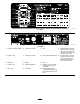
Controls Product Overview Become familiar with all the controls (Figure 4) before you start the engine and operate the traction unit. Control Panel g013016 Figure 4 1. Auxiliary hydraulics lever g004223 2. Key switch 7. Loader-arm/attachment-tilt lever 8. Parking-brake lever 3. Hour meter 4. Fuel gauge 9. Traction control 10. Reference bar 5. Indicator lights and glow-plug switch 11. Loader-control-reference bar 6. Throttle lever 12.
Traction Control • To turn right, rotate the traction control clockwise (Figure 8). g008128 g008131 Figure 5 Figure 8 1. Reference bar 2. Traction control • To turn left, rotate the traction control counterclockwise (Figure 9). • To move forward, move the traction control forward (Figure 6). g008132 Figure 9 g008129 • To stop the machine, release the traction control Figure 6 (Figure 5).
Loader Arm/Attachment-Tilt Lever • To tilt the attachment forward, slowly move the lever to the right (Figure 10). • To tilt the attachment rearward, slowly move the lever to the left (Figure 10). • To lower the loader arms, slowly move the lever forward (Figure 10). • To raise the loader arms, slowly move the lever g029981 rearward (Figure 10). Figure 11 • To lower the loader arms to a detent (float) 1. Loader arm/attachment-tilt lever position, push the lever fully forward (Figure 10). 2.
Parking-Brake Lever • To engage the parking brake, push the lever forward and to the left and then pull it rearward (Figure 13). Note: The traction unit may roll slightly before the brakes engage in the drive sprocket. • To release the brake, push the lever forward and then right, into the notch (Figure 13). g004350 Figure 14 1. Engine-oil pressure light 4. Battery-charge indicator light 2. Engine-coolant temperature light 5. Glow-plug light 3.
Specifications Operation Note: Specifications and design are subject to Note: Determine the left and right sides of the machine from the normal operating position. change without notice.
Filling the Fuel Tank(s) • Do not add or drain fuel in an enclosed space. • Do not store the machine or fuel container where there is an open flame, spark, or pilot light, such as on a water heater or other appliance. • If you spill fuel, do not attempt to start the engine; avoid creating any source of ignition until the fuel vapors have dissipated. 1. Park the machine on a level surface, engage the parking brake (if equipped), and lower the loader arms. 2.
During Operation • Slow down and use caution when making turns During Operation Safety • Stop the attachment when you are not working. • Stop the machine, turn off the engine, remove and crossing roads and sidewalks. Watch for traffic. General Safety the key, and inspect the machine if you strike an object. Make any necessary repairs before resuming operation. • Do not carry a load with the arms raised. Always • • • • • • • • • • • • • carry loads close to the ground.
(i.e., when the air temperature is at or below freezing) could damage the hydraulic system. When starting the engine in cold conditions, allow it to run in the middle throttle position for 2 to 5 minutes before moving the throttle to the FAST position. use common sense and good judgment when performing this survey. • Slow down and use extra care on hillsides. Ground conditions can affect the stability of the machine. • Avoid starting or stopping on a slope.
Using Attachments Installing an Attachment Important: Use only Toro-approved attachments. Attachments can change the stability and the operating characteristics of the machine. The warranty of the machine may be voided if you use the machine with unapproved attachments. Important: Before installing the attachment, ensure that the mount plates are free of any dirt or debris and that the pins rotate freely. If the pins do not rotate freely, grease them. 1.
Removing an Attachment Connecting the Hydraulic Hoses WARNING Hydraulic fluid escaping under pressure can penetrate skin and cause injury. Fluid injected into the skin must be surgically removed within a few hours by a doctor familiar with this form of injury; otherwise, gangrene may result. • Ensure that all hydraulic-fluid hoses and lines are in good condition and all hydraulic connections and fittings are tight before applying pressure to the hydraulic system.
Selecting a Trailer WARNING Loading a machine onto a trailer or truck increases the possibility of tip-over and could cause serious injury or death (Figure 19). • Use only a full-width ramp; do not use individual ramps for each side of the machine. • Ensure that the length of ramp is at least 4 times as long as the height of the trailer or truck bed to the ground. This ensures that ramp angle does not exceed 15 degrees on flat ground. g004181 Figure 18 1. Left tow valve (right track) 2.
Loading the Machine WARNING Loading a machine onto a trailer or truck increases the possibility of tip-over and could cause serious injury or death. • Use extreme caution when operating a machine on a ramp. • Load and unload the machine with the heavy end up the ramp. g243576 Figure 21 • Avoid sudden acceleration or deceleration while driving the machine on a ramp as this could cause a loss of control or a tip-over situation. 1.
Maintenance Note: Determine the left and right sides of the machine from the normal operating position. Recommended Maintenance Schedule(s) Maintenance Service Interval Maintenance Procedure After the first 8 hours • Replace the hydraulic filter. After the first 50 hours • Change the engine oil and filter. • Check and adjust the track tension. Before each use or daily • • • • • • • • • • • • Grease the machine. (Grease immediately after every washing.) Check the air-filter-service indicator.
CAUTION If you leave the key in the switch, someone could accidently start the engine and seriously injure you or other bystanders. Remove the key from the switch before you perform any maintenance. Pre-Maintenance Procedures Installing the Cylinder Lock 1. Remove the attachment. 2. Raise the loader arms to the fully raised position. Maintenance Safety 3. Shut off the engine and remove the key. • Park the machine on a level surface, disengage 4.
Accessing Internal Components Removing and Storing the Cylinder Lock Important: Remove the cylinder lock from the rod and fully secure it in the storage position before operating the machine. 1. Start the engine. 2. Raise the loader arms to the fully raised position. 3. Shut off the engine and remove the key. 4. Remove the lynch pin securing the cylinder lock. 5. Rotate the cylinder lock up to the loader arm and secure it with the lynch pin. 6. Lower the loader arms.
Closing the Rear-Access Cover Closing the Hood 1. Lift up on the tab securing the prop rod (Figure 25) 1. Move the rear-access cover in place over the back of the machine; ensure that the tabs line up in the slots. 2. Push the access cover forward, lining up the hand-knob screws with the threaded holes in the machine. 3. Screw the hand knobs tight to secure the rear-access cover in place. Removing the Side Screens 1. Open the hood. 2.
Lubrication Engine Maintenance Greasing the Machine Engine Safety Service Interval: Before each use or daily (Grease immediately after every washing.) • Shut off the engine before checking the oil or Grease Type: General-purpose grease. • Do not change the engine governor setting or 1. adding oil to the crankcase. overspeed the engine. Park the machine on a level surface, engage the parking brake (if equipped), and lower the loader arms. 2. Shut off the engine and remove the key. 3.
Important: Do not press on the soft inside area of the filter. 4. Install the air-cleaner cover with the dust cap oriented downward and secure the latches (Figure 30). 5. Close the hood. Servicing the Engine Oil Service Interval: Before each use or daily—Check the engine-oil level. g031236 After the first 50 hours—Change the engine oil and filter. Figure 30 1. Dust cap 4. Primary filter 2. Latch 5. Air-filter body 3. Air-cleaner cover 6. Service indicator 6.
Changing the Engine Oil Checking the Engine-Oil Level 1. Park the machine on a level surface, engage the parking brake, and lower the loader arms. 2. Shut off the engine, remove the key, and allow the engine to cool. 3. Open the hood. 4. Clean the area around the oil dipstick (Figure 32). 1. Start the engine and let it run for 5 minutes. Note: This warms the oil so that it drains better. 2.
Changing the Oil Filter 1. Drain the oil from the engine; refer to Changing the Engine Oil (page 27). 2. When the oil has drained completely, replace the plug. Fuel System Maintenance DANGER In certain conditions, fuel is extremely flammable and highly explosive. A fire or explosion from fuel can burn you and others and can damage property. Note: Dispose of the used oil at a certified recycling center. 3. Place a shallow pan or rag under the filter to catch oil. 4.
10. Locate the in-line filter to the left of the fuel filter canister (Figure 35) and note the direction of flow arrow on the side of the in-line filter. 11. Open the clamps on each end of the in-line filter and slide the hoses off it (Figure 35). Discard the filter. 12. Slide the hoses over the end of a new filter (Figure 35), ensuring that the arrow on the filter is pointing toward the engine or electric fuel pump. 13. Secure the hoses to the filter with the hose clamps. 14.
5. Turn the key in the key switch to the ON position. The electric fuel pump begins operation, thereby forcing air out around the air-bleed screw. Leave the key in the ON position until a solid stream of fuel flows out around the screw. Electrical System Maintenance 6. Tighten the screw and turn the key to the OFF position. Electrical System Safety • Disconnect the battery before repairing the Note: The engine should start after the above machine.
Servicing the Battery Always keep the battery clean and fully charged. Use a paper towel to clean the battery case. If the battery terminals are corroded, clean them with a solution of 4 parts water and 1 part baking soda. Apply a light coating of grease to the battery terminals to reduce corrosion. Specifications: 12 V, 585 A (cold cranking) Removing the Battery WARNING Battery terminals or metal tools could short against metal machine components, causing sparks.
Cleaning the Battery Note: Keep the terminals and the entire battery case clean, because a dirty battery discharges slowly. 1. Park the machine on a level surface, engage the parking brake (if equipped), and lower the loader arms. 2. Shut off the engine and remove the key. 3. Remove the battery from the machine; Removing the Battery (page 31). 4. Wash the entire case with a solution of baking soda and water. 5. Rinse the battery with clear water. 6.
Servicing the Fuses The electrical system is protected by fuses. It requires no maintenance; however, if a fuse blows, check the component/circuit for a malfunction or a short. Figure 40 illustrates the fuse block and identifies the fuse positions. g004984 Figure 41 1. Prop-rod tab 2. Retaining bracket—top 4. Retaining bracket—bottom 5. Hairpin cotter 3. Prop-rod 5. g004355 Remove the 4 screws securing the fuse panel and then pull the panel out and up to remove it (Figure 42). Figure 40 1.
Drive System Maintenance Servicing the Tracks Service Interval: After the first 50 hours—Check and adjust the track tension. Before each use or daily—Clean the tracks. Before each use or daily—Check the tracks for excessive wear (If the tracks are worn, replace them). g004200 Figure 43 Every 100 hours—Check and adjust the track tension. 1. Track 2. Drive sprocket 3. Road wheels 4. Tension wheel Every 250 hours/Yearly (whichever comes first)—Check and grease the road wheels.
g004202 Figure 45 1. Locking bolt 3. Tension tube 2. Tensioning screw 4. Tension wheel g004203 5. 6. 7. Figure 46 Using a 1/2-inch drive ratchet, turn the tensioning screw counterclockwise until the distance between the tension nut and the back of the tension tube (Figure 44) is 7 cm (2-3/4 inches). Align the closest notch in the tension screw to the locking bolt hole and secure the screw with the locking bolt and nut (Figure 45). 1. Track 5. Track lug 2. Socket wrench (1/2 inch) 6.
15. 9. Repeat steps 3 through 14 to replace the other track. 10. Pull the 4 large washers out of the 2 wheels, 1 on each side of each wheel. 11. Clean the old grease and dirt out of the area between where the washers were installed and the bearings inside the wheels, then fill this area on each side of each wheel with grease. 12. Install the large washers on the wheels over the grease. 13. Install the inner tension wheel and secure it with the nut removed previously (Figure 47). 14.
3. Cooling System Maintenance Remove the snap ring and cap from a road wheel (Figure 49). Cooling System Safety • Swallowing engine coolant can cause poisoning; keep out of reach from children and pets. • Discharge of hot, pressurized coolant or touching a hot radiator and surrounding parts can cause severe burns. – Always allow the engine to cool at least 15 minutes before removing the radiator cap. g004206 – Use a rag when opening the radiator cap, and open the cap slowly to allow steam to escape.
Checking, Adding, and Bleeding the Engine Coolant The cooling system is filled with a 50/50 solution of water and permanent ethylene-glycol antifreeze. 1. Park the machine on a level surface, lower the loader arms, engage the parking brake, and shut off the engine. 2. Remove the key from the key switch and allow the engine to cool. 3. Check the coolant level of coolant in the expansion tank (Figure 50). The coolant level should be at or above the mark on the side of the tank. g004230 Figure 51 1.
Brake Maintenance Belt Maintenance Testing the Parking Brake Checking the Condition of the Hydraulic Pump Belt Service Interval: Before each use or daily 1. Engage the parking-brake; refer to Parking-Brake Lever (page 12). 2. Start the engine. 3. Slowly attempt to drive the machine forward or rearward. Service Interval: Yearly Check the condition of the hydraulic pump belt (Figure 52) yearly. Have an Authorized Service Dealer replace it if it becomes damaged or worn.
Controls System Maintenance Adjusting the Controls The factory adjusts the controls before shipping the machine. However, after many hours of use, you may need to adjust the traction control alignment, the NEUTRAL position of the traction control, and the tracking of the traction control in the full forward position. g004191 Figure 54 1. Traction control Important: To adjust the controls properly, 5. complete each procedure in the order listed. 2.
Adjusting the Tracking of the Traction Control, Full Forward Position If the machine does not drive straight when you hold the traction control against the reference bar, complete the following procedure: 1. Drive the machine with the traction control against the reference bar, noting which direction the traction unit veers. 2. Release the traction control. 3.
Hydraulic System Maintenance Material Properties Viscosity, ASTM D445 cSt at 40°C: 55 to 62 cSt at 100°C: 9.1 to 9.8 Viscosity index, ASTM D2270 140 to 152 Hydraulic System Safety Pour Point, ASTM D97 -37 to -43°C (-35 to -46°F) • Seek immediate medical attention if fluid is injected Industry Standards into skin. Injected fluid must be surgically removed within a few hours by a doctor. API GL-4, AGCO Powerfluid 821 XL, Ford New Holland FNHA-2-C-201.
Replacing the Hydraulic Filter Service Interval: After the first 8 hours Every 200 hours Important: Do not substitute an automotive oil filter or severe hydraulic system damage may result. 1. Park the machine on a level surface, engage the parking brake, and lower the loader arms. 2. Shut off the engine and remove the key. 3. Open the rear access cover. 4. Place a drain pan under the filter (Figure 60). g004226 Figure 58 1. Filler-neck cap 6.
Changing the Hydraulic Fluid Service Interval: Every 400 hours/Yearly (whichever comes first) 1. Park the machine on a level surface. 2. Raise the loader arms and install the cylinder lock. 3. Shut off the engine, remove the key, and allow the engine to cool. 4. Open the hood. 5. Remove the hydraulic-tank cap and dipstick (Figure 61). Note: The filler cap is behind the front screen. g004213 If you want to improve your access to it, remove the screen. Figure 62 1. Drain plug 7.
Cleaning Storage Removing Debris Storage Safety Service Interval: Before each use or daily • Allow the machine to cool before storing. • Do not store the machine or fuel near flames. Important: Operating the engine with blocked screens and/or cooling shrouds removed will result in engine damage from overheating. 1. Park the machine on a level surface and lower the loader arms. 2. Storage 1. Shut off the engine, remove the key, and allow the engine to cool.
Troubleshooting Problem The starter does not crank. The engine cranks but does not start. Possible Cause Corrective Action 1. The electrical connections are corroded or loose. 1. Check the electrical connections for good contact. 2. A fuse is loose or blown. 3. The battery is discharged. 4. The relay or switch is damaged. 5. A starter or starter solenoid is damaged. 6. Internal engine components have seized. 2. Connect or replace the fuse. 3. Charge the battery or replace it. 4.
Problem The engine starts but does not keep running. Possible Cause 1. The fuel-tank vent is restricted. 1. Loosen the cap. If the engine runs with the cap loosened, replace the cap. 2. Dirt or water is in the fuel system. 2. Drain and flush the fuel system; add fresh fuel. 3. Replace the fuel filter. 4. Bleed the nozzles and check for air leaks at fuel hose connections and fittings between the fuel tank and engine. 5. Drain the fuel system and replace the fuel filter.
Problem The engine overheats. Possible Cause 1. More coolant is needed. 1. Check and add coolant. 2. There is restricted air flow to the radiator. 3. The crankcase-oil level is incorrect. 4. The engine load is excessive. 2. Inspect and clean the radiator screen with every use. 3. Fill or drain to the Full mark. 4. Reduce the load; use a lower ground speed. 5. Drain and flush the fuel system; add fresh fuel. 6. Contact your Authorized Service Dealer. 7. Contact your Authorized Service Dealer. 8.
Problem Exhaust produces excessive white smoke. Possible Cause 1. The key was turned to the START position before the glow-plug light turned off. 1. Turn the key to the RUN position and allow the glow-plug light to turn off before starting the engine. 2. The engine temperature is low. 3. The glow plugs are inoperative. 4. The injection-pump timing is incorrect. 2. Check the thermostat. 3. Check the fuse, glow plugs and wiring. 4. Contact your Authorized Service Dealer. 5.
Schematics g007388 Electrical Schematic (Rev.
g243502 Hydraulic Schematic (Rev.
Notes:
Notes:
European Privacy Notice The Information Toro Collects Toro Warranty Company (Toro) respects your privacy. In order to process your warranty claim and contact you in the event of a product recall, we ask you to share certain personal information with us, either directly or through your local Toro company or dealer. The Toro warranty system is hosted on servers located within the United States where privacy law may not provide the same protection as applies in your country.