Form No. 3372-647 Rev E TX 525 Compact Utility Loader Model No. 22323—Serial No. 312000001 and Up Model No. 22324—Serial No. 312000001 and Up G004222 Register at www.Toro.com.
You may contact Toro directly at www.Toro.com for product and accessory information, help finding a dealer, or to register your product. This product complies with all relevant European directives, for details please see the separate product specific Declaration of Conformity (DOC) sheet. Whenever you need service, genuine Toro parts, or additional information, contact an Authorized Service Dealer or Toro Customer Service and have the model and serial numbers of your product ready.
Contents Checking the Condition of the Hydraulic Pump Belt...................................................................40 Checking the Alternator/Fan Belt Tension .................40 Controls System Maintenance .....................................40 Adjusting the Traction Control Alignment .................40 Adjusting the Traction Control Neutral Position .............................................................41 Adjusting the Tracking of the Traction Control, Full Forward Position ...........
Safety • Improper use or maintenance by the operator or owner can result in injury. To reduce the potential for injury, comply with these safety instructions and always pay attention to the safety alert symbol , which means: Caution, Warning, or Danger—personal safety instruction. Failure to comply with the instruction may result in personal injury or death. Operation • Never run an engine in an enclosed area.
• Do not over-load the attachment and always keep the • • • • • • • • • terrain could overturn the traction unit. Tall grass can hide obstacles. load level when raising the loader arms. Logs, boards, and other items could roll down the loader arms, injuring you. Never jerk the controls; use a steady motion. Watch for traffic when operating near or crossing roadways. Do not touch parts which may be hot from operation. Allow them to cool before attempting to maintain, adjust, or service.
• Secure the loader arm valve with the loader valve lock The sound power level was determined according to the procedures outlined in ISO 6395. anytime you need to stop the machine with the loader arms raised. • Keep nuts and bolts tight. Keep equipment in good Vibration Level condition. Measured vibration level for right hand = 1.5 m/s2 • Never tamper with safety devices. • Keep the traction unit free of grass, leaves, or other debris Measured vibration level for left hand = 1.3 m/s2 build-up.
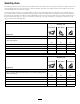
Stability Data The following tables list the maximum slope recommended for the traction unit in the positions listed in the tables. Slopes over the listed degree may cause the traction unit to become unstable. The data in the tables assume that the loader arms are fully lowered; raised arms may affect the stability. In each attachment manual is a set of three stability ratings, one for each hill position.
Slope Indicator G011841 Figure 3 This page may be copied for personal use. 1. To determine the maximum slope you can safely operate the machine on, refer to the Stability Data section. Use the slope indicator to determine the degree of slope of hills before operating. Do not operate this machine on a slope greater than that specified in the Stability Data section. Fold along the appropriate line to match the recommended slope. 2. Align this edge with a vertical surface, a tree, building, fence pole, etc.
Safety and Instructional Decals Safety decals and instructions are easily visible to the operator and are located near any area of potential danger. Replace any decal that is damaged or lost. 93-6681 1. Cutting/dismemberment—hazard, fan-stay away from moving parts. 100-4650 1. Crushing hazard of hand—keep bystanders a safe distance from the machine. 2. Crushing hazard of foot—keep bystanders a safe distance from the machine. 93-9084 1. Lift point 2. Tie-down point 100-8821 1.
115-4858 1. Crushing hazard of hands or feet—install the cylinder lock. 115-4857 1. Lower the loader arms. 2. Dump the bucket. 106-6755 1. Engine coolant under pressure. 3. Warning—do not touch the hot surface. 2. Explosion hazard—read the Operator's Manual. 4. Warning—read the Operator's Manual. 4. Curl the bucket. 5. Float the bucket on the ground. 3. Raise the loader arms. 115-4859 115-4020 1. Turn right 3. Reverse 2. Forward 4. Turn left 1. Disengaged 3. Engaged 2.
5-4862 1. Loader valve lock, unlocked 2. Loader valve lock, locked 115-4860 1. Warning—read the Operator's Manual. 2. Warning—set the parking brake, stop the engine, remove the ignition key and lower the loader arms before leaving the machine. 3. Crushing hazard—install the cylinder lock and read the instructions before servicing or performing maintenance. 4. Cutting hazard of hands or feet—wait for all moving parts to stop; stay away from moving parts; keep all guards and shields in place. 5.
117–9905 1. Operator's Manual location 6. Fuel gauge—diesel 2. Engine—start 7. Engine oil pressure 16. Tipping hazard—move the traction unit with the heavy end up hill; do not travel with the loader arms raised. 12. Continuous variable setting 17. Tipping hazard—slow the traction unit when turning, do not travel fast when turning, look behind and down when reversing. 3. Engine—run 8. Battery 13. Slow 4. Engine—stop 9. Engine temperature 14.
Controls Product Overview Become familiar with all the controls (Figure 5) before you start the engine and operate the traction unit. 1 2 3 4 5 9 g013016 6 10 7 11 8 12 Figure 5 1. Auxiliary hydraulics lever 2. Key switch 12 7. Loader arm/attachment tilt lever 8. Parking brake lever 3. Hour meter 4. Fuel gauge 9. Traction control 10. Reference bar 5. Indicator lights and glow plug switch 11. Loader control reference bar 6. Throttle lever 12.
Traction Control G008131 Figure 9 Figure 6 • To turn left, rotate the traction control counterclockwise (Figure 10). 1. Reference bar (does not move to give you a reference point and a fixed handle to hold while operating the traction unit) 2. Traction control (moves to control the machine) • To move forward, move the traction control forward (Figure 7). G008132 Figure 10 • To stop, release the traction control (Figure 6).
Auxiliary Hydraulics Lever To operate a hydraulic attachment in the forward direction, rotate the auxiliary hydraulics lever rearward and pull it down to the reference bar (Figure 13, number 1). To operate a hydraulic attachment in reverse direction, rotate the hydraulics lever rearward, then move it left into the upper slot (Figure 13, number 2). If you release the lever while in the forward position, the lever will automatically return to the neutral position (Figure 13, number 3).
Specifications immediately and check the oil. If low, add oil and/or look for possible leaks. 1 2 4 Note: Specifications and design are subject to change without notice. 3 5 Figure 15 Model 22323 Width Length Height Weight Operating capacity Tipping capacity Wheelbase Dump height (with narrow bucket) Reach—fully raised (with narrow bucket) Height to hinge pin (narrow bucket in highest position) G004350 1. Engine oil pressure light 4. Battery charge indicator light 2.
Operation • Monitor seals, hoses, gaskets in contact with fuel as they Note: Determine the left and right sides of the machine from the normal operating position. • Fuel filter plugging may be expected for a time after Important: Before operating, check the fuel and oil level, and remove debris from the traction unit. Also, ensure that the area is clear of people and debris. You should also know and have marked the locations of all utility lines.
Checking the Engine Oil Level 1. Remove the fuel tank cap (Figure 16). Service Interval: Before each use or daily 1. Park the traction unit on a level surface, lower the loader arms, and stop the engine. 2. Remove the key and allow the engine to cool. 3. Open the hood. 4. Clean around the oil dipstick (Figure 17). Figure 16 1. Fuel tank cap 2. Fill the tank to about one inch below the top of the tank, not the filler neck, with diesel fuel. 3. Install the fuel tank cap. Figure 17 1. Oil dipstick 2.
Checking the Hydraulic Fluid Level Service Interval: Every 25 hours Hydraulic Tank Capacity: 12 US gallons (45.4 l) Refer to Changing the Hydraulic Fluid (page 43) for hydraulic fluid specifications. Important: Always use the correct hydraulic fluid. Unspecified fluids will damage the hydraulic system. 1. Remove the attachment, if one is installed; refer to Removing an Attachment. 2. Park the traction unit on a level surface, lower the loader arms, and fully retract the tilt cylinder. Figure 19 3.
Checking, Adding, and Bleeding the Engine Coolant Service Interval: Before each use or daily Clean debris off of the screen, oil cooler, and front of the radiator daily and more often if conditions are extremely dusty and dirty The cooling system is filled with a 50/50 solution of water and permanent ethylene glycol antifreeze. Check the level of coolant in the expansion tank at the beginning of each day before starting the engine.
F. Close the top coolant bleed valve (Figure 21). G. Pour coolant into the coolant filler neck until the coolant level comes into the filler neck (Figure 21). H. Install the coolant fill cap (Figure 21). I. Add coolant into the expansion tank until it reaches the Full line on the side of the tank (Figure 21). 3. Install the expansion tank cap.
hydraulic system damage could occur. When starting the engine in cold conditions, allow the engine to run in the middle throttle position for 2 to 5 minutes before moving the throttle to fast (rabbit). Note: If outdoor temperature is below freezing, store the traction unit in a garage to keep it warmer and aid in starting. Stopping the Engine 1. Move the throttle lever to the slow (turtle) position. 2. Lower the loader arms to the ground. 3. Turn the ignition key off.
Important: Before installing the attachment, ensure that the mount plates are free of any dirt or debris and that the pins rotate freely. If the pins do not rotate freely, grease them. 1 1. Position the attachment on a level surface with enough space behind it to accommodate the traction unit. 2. Start the engine. 3. Tilt the attachment mount plate forward. 3 4. Position mount plate into the upper lip of the attachment receiver plate (Figure 25). G004182 2 Figure 24 1. Cylinder lock 3. Lynch pin 2.
Note: When you connect the attachment male connector first, you will relieve any pressure built up in the attachment. WARNING Hydraulic fluid escaping under pressure can penetrate skin and cause injury. Fluid injected into the skin must be surgically removed within a few hours by a doctor familiar with this form of injury or gangrene may result. • Keep your body and hands away from pin hole leaks or nozzles that eject high pressure hydraulic fluid.
Securing the Traction Unit for Transport When transporting the traction unit on a trailer, always use the following procedure: Important: Do not operate or drive the traction unit on roadways. 1. Lower the loader arms. 2. Stop the engine. 3. Secure the traction unit to the trailer with chains or straps using the tie-down/lift loops (Figure 4) to secure the rear of the traction unit and the loader arms/mount plate to secure the front of the traction unit.
Maintenance Note: Determine the left and right sides of the machine from the normal operating position. Recommended Maintenance Schedule(s) Maintenance Service Interval Maintenance Procedure After the first 8 hours • Replace the hydraulic filter. After the first 50 hours • Change the engine oil and filter. • Check and adjust the track tension. Before each use or daily • • • • • • • • • • Check the engine oil level. Check the cooling system. Grease the traction unit.
CAUTION If you leave the key in the ignition switch, someone could accidently start the engine and seriously injure you or other bystanders. Remove the key from the ignition before you do any maintenance. Premaintenance Procedures Closing the Hood 1. Lift up on the tab securing the prop-rod (Figure 28) Before opening any of the covers, stop the engine and remove the key. Allow the engine to cool before opening any covers Opening the Hood 1. Loosen the hood locking screw (Figure 27) Figure 28 1.
Opening the Rear Access Cover Removing the Side Screens 1. Open the hood. 2. Slide the side screens (Figure 30) up and out of the slots in the front screen and frame. 1. Unscrew the 2 hand knobs securing the rear access cover to the machine (Figure 29). Figure 29 1. Hand knobs 2. Tilt the rear access cover down and remove to access the internal components (Figure 29). Figure 30 1. Side screen Closing the Rear Access Cover 1.
Lubrication Engine Maintenance Greasing the Traction Unit Servicing the Air Cleaner Service Interval: Before each use or daily (Grease immediately after every washing.) Service Interval: Before each use or daily—Check the air filter service indicator. Every 25 hours—Remove air cleaner cover, clean out debris, and check the air filter service indicator. Grease Type: General-purpose grease. 1. Lower the loader arms and stop the engine. Remove the key. Every 600 hours—Replace the safety air filter. 2.
Servicing the Engine Oil Ensure that the cover is seated correctly and seals with the air cleaner body. Service Interval: After the first 50 hours—Change the engine oil and filter. • If the service indicator is red, replace the air filter as described in Replacing the Filters. Every 100 hours—Change the engine oil. Replacing the Filters Every 200 hours—Change the oil filter. Note: Change oil and oil filter more frequently when operating conditions are extremely dusty or sandy. 1.
Figure 35 Figure 36 1. Oil drain plug 1. Oil filter 5. When the oil has drained completely, replace the plug. 4. Pour new oil of the proper type through the center hole of the filter. Stop pouring when the oil reaches the bottom of the threads. Note: Dispose of the used oil at a certified recycling center. 5. Allow a minute or two for the oil to be absorbed by filter material, then pour off the excess oil. 6.
Fuel System Maintenance DANGER Under certain conditions, diesel fuel and fuel vapors are highly flammable and explosive. A fire or explosion from fuel can burn you and others and can cause property damage. • Use a funnel and fill the fuel tank outdoors, in an open area, when the engine is off and is cold. Wipe up any fuel that spills. • Do not fill the fuel tank completely full. Add fuel to the fuel tank until the level is 1/4 to 1/2 in. (6 to 13 mm) below the bottom of the filler neck.
Electrical System Maintenance 9. Secure the hoses with the hose clamps. Draining the Fuel Tank Service Interval: Every 2 years Servicing the Battery Have an Authorized Service Dealer drain and clean the fuel tank. Service Interval: Every 100 hours—Check the battery electrolyte level (replacement battery only). Every 100 hours—Check the battery cable connections.
6. Install the battery filler caps. Charging the Battery 2 WARNING 3 Charging the battery produces gasses that can explode. 1 Never smoke near the battery and keep sparks and flames away from battery. G003794 Figure 38 1. Filler caps Important: Always keep the battery fully charged (1.265 specific gravity). This is especially important to prevent battery damage when the temperature is below 32°F (0°C). 3. Lower line 2. Upper line 1.
Figure 41 1. Prop-rod tab Figure 40 1. 30 amp. fuse—main circuit 3. 10 amp fuse—control panel/relay 2. Empty 4. Open position for optional accessories 2. Retaining bracket—top 4. Retaining bracket—bottom 5. Hairpin cotter 3. Prop-rod 4. Remove the 4 screws securing the fuse panel and then pull the panel out and up to remove it (Figure 42). Note: If the traction unit will not start, either the main circuit or control panel/relay fuse could be blown.
Adjusting the Track Tension Drive System Maintenance There should be 2-3/4 inches (7 cm) between the tension nut and the back of the tension tube (Figure 44). If not, adjust the track tension using the following procedure: Servicing the Tracks Service Interval: After the first 50 hours—Check and adjust the track tension. Before each use or daily—Clean the tracks. Before each use or daily—Check the tracks for excessive wear (If the tracks are worn, replace them.
Replacing the Tracks (Model 22323) 11. Turn the tensioning screw counter-clockwise until the distance between the tension nut and the back of the fork tube (Figure 44) is 2-3/4 inches (7 cm). When the tracks are badly worn, replace them. 1. Lower the loader arms, stop the engine, and remove the key. 12. Align the closest notch in the tension screw to the locking bolt hole and secure the screw with the locking bolt and nut. 2.
7. Remove the track (Figure 47). 8. Remove the nut securing the inner tension wheel and remove the wheel (Figure 47). 9. Pull the 4 large washers out of the 2 wheels, 1 on each side of each wheel. 10. Clean the old grease and dirt out of the area between where the washers were installed and the bearings inside the wheels, then fill this area on each side of each wheel with grease. 11. Install the large washers on the wheels over the grease. 12.
Cooling System Maintenance If you need to add engine coolant, refer to Checking, Adding, and Bleeding the Engine Coolant (page 20). Servicing the Cooling System Service Interval: Before each use or daily—Clean the radiator. Every 100 hours—Check the cooling system hoses. Yearly—Change the engine coolant (Authorized Service Dealer only). DANGER If the engine has been running, the pressurized, hot coolant can escape and cause severe burns. • Do not remove the radiator cap when the engine is hot.
Belt Maintenance Controls System Maintenance Checking the Condition of the Hydraulic Pump Belt The factory adjusts the controls before shipping the traction unit. However, after many hours of use, you may need to adjust the traction control alignment, the neutral position of the traction control, and the tracking of the traction control in the full forward position. Service Interval: Yearly Check the condition of the hydraulic pump belt (Figure 50) yearly.
5. Adjust the traction control so that it rests flush against the reference bar when it is pulled straight back (Figure 52 and Figure 53). WARNING When the traction unit is running, you could be caught and injured in moving parts or burned on hot surfaces. Stay away from pinch points, moving parts, and hot surfaces when adjusting the running traction unit. 5. If the left track moves, lengthen or shorten the right traction rod until the track stops moving. Figure 53 6.
Hydraulic System Maintenance Replacing the Hydraulic Filter Service Interval: After the first 8 hours Every 200 hours Important: Do not substitute an automotive oil filter or severe hydraulic system damage may result. 1. Position traction unit on a level surface. Figure 55 1. Set screw 2. Lower the loader arms, stop the engine, and remove the key. 3. Stop 2. Jam nut 3. Open the rear access cover. 4. Place a drain pan under the filter (Figure 56). 5.
WARNING Industry Standards API GL-4, AGCO Powerfluid 821 XL, Ford New Holland FNHA-2-C-201.00, Kubota UDT, John Deere J20C, Vickers 35VQ25 and Volvo WB-101/BM. Hydraulic fluid escaping under pressure can penetrate skin and cause injury. Fluid injected into the skin must be surgically removed within a few hours by a doctor familiar with this form of injury or gangrene may result. Note: Many hydraulic fluids are almost colorless, making it difficult to spot leaks.
Checking the Hydraulic Lines Service Interval: Every 100 hours—Check the hydraulic lines for leaks, loose fittings, kinked lines, loose mounting supports, wear, weather, and chemical deterioration. (Make necessary repairs before operating.) Every 1,500 hours/Every 2 years (whichever comes first)—Replace all moving hydraulic hoses. WARNING Hydraulic fluid escaping under pressure can penetrate skin and cause injury.
Cleaning Storage 1. Lower the loader arms, stop the engine, and remove the key. Removing Debris from the Traction Unit 2. Remove dirt and grime from the entire traction unit. Important: You can wash the traction unit with mild detergent and water. Do not pressure wash the traction unit. Avoid excessive use of water, especially near the control panel, engine, hydraulic pumps, and motors.
Troubleshooting Problem The starter does not crank Possible Cause 1. The electrical connections are corroded or loose. 1. Check the electrical connections for good contact. 2. A fuse is blown or loose. 3. The battery is discharged. 4. The relay or switch is damaged. 2. Correct or replace the fuse. 3. Charge the battery or replace it. 4. Contact your Authorized Service Dealer. 5. Contact your Authorized Service Dealer. 6. Contact your Authorized Service Dealer. 5. A damaged starter or starter solenoid.
Problem The engine runs, but knocks or misses. Possible Cause 1. Dirt, water, stale fuel, or incorrect fuel is in the fuel system. 1. Drain and flush the fuel system; add fresh fuel. 2. Engine overheating. 3. There is air in the fuel. 2. Refer to Engine Overheats. 3. Bleed nozzles and check for air leaks at the fuel hose connections and fittings between the fuel tank and engine. 4. Contact your Authorized Service Dealer. 5. Contact your Authorized Service Dealer. 6.
Problem Excessive white smoke from exhaust. Possible Cause 1. The key was turned to the start position before the glow plug light turned off. 1. Turn the key to the run position and allow the glow plug light to turn off before starting the engine. 2. The engine temperature is low. 3. The glow plugs are inoperative. 4. The injection pump timing is incorrect. 2. Check the thermostat. 3. Check the fuse, glow plugs and wiring. 4. Contact your Authorized Service Dealer. 5.
Schematics G007388 Electrical Schematic (Rev.
Hydraulic Schematic (Rev.
Notes: 51
Toro Compact Utility Equipment Warranty A One-Year Limited Warranty Conditions and Products Covered The Toro® Company and its affiliate, Toro Warranty Company, pursuant to an agreement between them, jointly warrant your Toro Compact Utility Equipment (“Product”) to be free from defects in materials or workmanship.