Form No. 3412-407 Rev A TX 1000 Compact Tool Carrier Model No. Model No. Model No. Model No. Register at www.Toro.com. Original Instructions (EN) 22327—Serial No. 400000000 and Up 22327G—Serial No. 400000000 and Up 22327HD—Serial No. 400000000 and Up 22328—Serial No.
This product complies with all relevant European directives; for details, please see the separate product specific Declaration of Conformity (DOC) sheet. WARNING CALIFORNIA Proposition 65 Warning This product contains a chemical or chemicals known to the State of California to cause cancer, birth defects, or reproductive harm. The engine exhaust from this product contains chemicals known to the State of California to cause cancer, birth defects, or other reproductive harm.
Contents Controls System Maintenance .....................................40 Hydraulic System Maintenance ....................................41 Replacing the Hydraulic Filter ..................................41 Changing the Hydraulic Fluid...................................41 Checking the Hydraulic Lines...................................43 Cleaning ...................................................................43 Removing Debris from the Traction Unit ...................43 Cleaning the Chassis .....
Safety • Improper use or maintenance by the operator or owner can result in injury. To reduce the potential for injury, comply with these safety instructions and always pay attention to the safety-alert symbol , which means: Caution, Warning, or Danger—personal safety instruction. Failure to comply with the instruction may result in personal injury or death.
• Watch for traffic when operating near or crossing • • • • roadways. Do not touch parts which may be hot from operation. Allow them to cool before attempting to maintain, adjust, or service. Check for overhead clearances (i.e., branches, doorways, electrical wires) before driving under any objects and do not contact them. Ensure that you operate the traction unit in areas where there are no obstacles in close proximity to the operator.
Sound Pressure Level • Use extra care when handling fuels. They are flammable and vapors are explosive. Sound Pressure Level This unit has a sound pressure level at the operator’s ear of 86 dBA, which includes an Uncertainty Value (K) of 0.6 dBA. – Use only an approved container. – Never remove the fuel cap or add fuel when the engine is running. Allow the engine to cool before refueling. Do not smoke. Sound pressure level was determined according to the procedures outlined in ISO 6396.
Stability Data The following tables list the maximum slope recommended for the traction unit in the positions listed in the tables. Slopes over the listed degree may cause the traction unit to become unstable. The data in the tables assume that the loader arms are fully lowered; raised arms may affect the stability. In each attachment manual is a set of three stability ratings, one for each hill position.
Slope Indicator G011841 g011841 Figure 3 This page may be copied for personal use. 1. To determine the maximum slope you can safely operate the machine on, refer to the Stability Data section. Use the slope indicator to determine the degree of slope of hills before operating. Do not operate this machine on a slope greater than that specified in the Stability Data section. Fold along the appropriate line to match the recommended slope. 2.
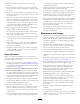
Safety and Instructional Decals Safety decals and instructions are easily visible to the operator and are located near any area of potential danger. Replace any decal that is damaged or lost. decal93-6681 93-6681 decal115-2047 115-2047 1. Cutting/dismemberment hazard, fan—stay away from moving parts. 1. Warning—do not touch the hot surface. decal93-7814 93-7814 decal115-4855 115-4855 1. Entanglement hazard, belt—stay away from moving parts. 1.
decal120-0625 120-0625 1. Pinch point, hand—keep hands away. decal131-0711 131-0711 1. Crushing hazard—keep away from pinch points and actuating parts. decal130-2836 130-2836 1. Crushing hazard; cutting hazard—keep away from the bucket and the lift arm. decal130-7637 decal131-8026 130-7637 131-8026 1. Blinking light—engine-coolant temperature 6. Engine start 2. Steady light—engine-oil pressure 7. Parking brake disengaged 3. Blinking light—glow plug 8. Traction neutral 4.
decal131-0707 131-0707 1. 12 V power socket 7. Tilt the attachment forward. 2. Hydraulic attachment—forward operation 8. Tilt the attachment rearward. 3. Hydraulic attachment—neutral position 4. Hydraulic attachment—reverse operation 9. Lower the attachment. 10. Raise the attachment. 5. Engine speed—fast 11. Move the attachment to a float position. 6. Engine speed—slow 12. Lever lock decal131-0708 131-0708 3. Move rearward 4. Turn left 1. Move forward 2.
decal131-0710 131-0710 1. Warning—read the Operator's Manual. 7. Cutting/severing hazard of hand or foot—wait for all moving parts to stop before servicing; keep away from moving parts; keep all guards and shields in place. 2. Warning—receive training before operating the machine. 8. Explosion hazard; electrocution hazard—call the local utilities hotline before beginning work in an area. 3. Warning—wear hearing protection. 9.
Controls Product Overview Become familiar with all the controls (Figure 5) before you start the engine and operate the traction unit. g029284 Figure 5 1. Message display 6. Key switch 2. Power socket 3. Reference bar 7. Traction control 8. Loader arm/attachment-tilt lever 9. Loader lock 4. Auxiliary-hydraulics lever 5. Throttle lever g031208 Key Switch The key switch, used to start and shut off the engine, has 3 positions: OFF, RUN, and START.
Traction Control • To turn right, rotate the traction control clockwise (Figure 9). g029289 Figure 6 g029288 1. Reference bar 2. Traction control Figure 9 • To turn left, rotate the traction control counterclockwise • To move forward, move the traction control forward (Figure 10). (Figure 7). g029287 g029285 Figure 10 Figure 7 • To stop the machine, release the traction control (Figure • To move rearward, move the traction control rearward 6). (Figure 8).
Loader Arm/Attachment-Tilt Lever Loader Lock • To tilt the attachment forward, slowly move the lever to The loader lock secures the loader arm/attachment-tilt lever so that you cannot push it forward. This ensures that no one accidentally lowers the loader arms during maintenance. Secure the loader arms with the lock any time you need to stop the machine with the loader arms raised. the right (Figure 11). • To tilt the attachment rearward, slowly move the lever to the left (Figure 11).
Auxiliary-Hydraulics-Lock Switch Engine-Oil Pressure Press the auxiliary-hydraulics-lock switch to lock the auxiliary-hydraulics lever in the FORWARD position and free your hand for other controls (Figure 5). If the engine-oil-pressure becomes too low, the light on the left illuminates steadily (Figure 16). If this happens, shut off the engine immediately and check the oil. If the oil level is low, add oil and/or look for possible leaks.
Specifications • Parking brake—displays when you disengage the parking brake Note: Specifications and design are subject to change without notice.
Adding Fuel Operation Use only clean, fresh diesel fuel or biodiesel fuels with low (<500 ppm) or ultra low (<15 ppm) sulfur content. The minimum cetane rating should be 40. Purchase fuel in quantities that can be used within 180 days to ensure fuel freshness. Note: Determine the left and right sides of the machine from the normal operating position. Important: Before operating, check the fuel and oil level, and remove debris from the traction unit. Ensure that the area is clear of people and debris.
Filling the Fuel Tanks Fill the fuel tanks as shown in Figure 24. Note: The fuel-tank caps click when you close them securely. Use the brackets to lock the fuel tanks. DANGER In certain conditions, fuel is extremely flammable and highly explosive. A fire or explosion from fuel can burn you and others and can damage property. • Fill the fuel tanks outdoors, in an open area, when the engine is cold. Wipe up any fuel that spills. • Never fill the fuel tanks inside an enclosed trailer.
Checking the Engine-Oil Level Checking the Hydraulic-Fluid Level Service Interval: Before each use or daily 1. Park the traction unit on a level surface, lower the loader arms, and shut off the engine. Service Interval: Every 25 hours Hydraulic Tank Capacity: 37.9 L (10 US gallons) 2. Remove the key and allow the engine to cool. Refer to Changing the Hydraulic Fluid (page 41) for hydraulic fluid specifications. 3. Open the hood and secure the hood prop. 4.
DANGER Rotating shaft and fan can cause personal injury. • Do not operate the machine without the covers in place. • Keep fingers, hands, and clothing clear of rotating fan and drive shaft. • Shut off the engine and remove the ignition key before performing maintenance. 1. Check the level of coolant in the expansion tank (Figure 29). g029729 Note: The coolant level should be at or above the mark on the side of the tank. Figure 28 1. Filler neck 2. Dipstick 9.
Bleeding the Fuel System Leave the key in the ON position until a solid stream of fuel flows out around the screw. You must bleed the fuel system before starting the engine if any of the following situations have occurred: • Initial start up of a new machine. • Engine has ceased running due to lack of fuel. • Maintenance has been performed upon fuel-system components (e.g., filter replaced). 5. Tighten the screw and turn the key to the OFF position.
Stopping the Machine 5. Tow the traction unit as required. Stop the machine on level ground, release the traction control, move the throttle lever to the SLOW position, lower the loader arms to the ground, and shut off the engine. Set the parking brake and remove the key. 6. After repairing the machine, close the tow valves before operating it. CAUTION A child or untrained bystander could attempt to operate the traction unit and be injured.
Using Attachments Installing an Attachment Important: Use only Toro-approved attachments. Attachments can change the stability and the operating characteristics of the traction unit. The warranty of the traction unit may be voided if used with unapproved attachments. Important: Before installing the attachment, ensure that the mount plates are free of any dirt or debris and that the pins rotate freely. If the pins do not rotate freely, grease them. 1.
Securing the Machine for Transport CAUTION Hydraulic couplers, hydraulic lines/valves, and hydraulic fluid may be hot. If you contact hot components, you may be burned. Use a heavy-duty trailer or truck to transport the machine. Use full-width ramps. Ensure that the trailer or truck has all the necessary brakes, lighting, and marking as required by law. Please carefully read all the safety instructions. Knowing this information could help you, your family, pets or bystanders avoid injury.
Maintenance Note: Determine the left and right sides of the machine from the normal operating position. Recommended Maintenance Schedule(s) Maintenance Service Interval Maintenance Procedure After the first 8 hours • Replace the hydraulic filter. After the first 50 hours • Change the engine oil and filter. • Check and adjust the track tension. Before each use or daily • Check the engine-oil level. • Check the level of coolant in the expansion tank.
CAUTION If you leave the key in the ignition switch, someone could accidently start the engine and seriously injure you or other bystanders. Remove the key from the ignition before you do any maintenance. Pre-Maintenance Procedures Removing/Storing the Cylinder Locks Important: Remove the cylinder locks from the rod and fully secured in the storage position before operating the traction unit. Before opening any of the covers, shut the engine and remove the key.
Removing the Front Screen Closing the Hood 1. Open the hood and secure the hood prop. 1. Lift up on the tab securing the prop-rod (Figure 37) 2. Loosen the 2 top bolts and 2 front bolts. g031216 Figure 37 1. Prop-rod tab 2. Lower the hood and secure it by pushing down on the front of the hood until it locks in place. 3. Tighten the hood-locking screw to secure the latch (Figure 36). g031218 Figure 39 1. Bolt Opening the Rear-Access Cover 3. Remove the screen. 1. Remove the fastener (Figure 38).
Lubrication Greasing the Machine Service Interval: Before each use or daily (Grease immediately after every washing.) Grease Type: General-purpose grease. 1. Lower the loader arms and shut off the engine. Remove the key. 2. Clean the grease fittings with a rag. 3. Connect a grease gun to each fitting (Figure 41, Figure 42, and Figure 43). g029953 Note: Raise the loader arms before greasing the fittings in Figure 43. Figure 43 4.
Engine Maintenance • If the service indicator is clear, clean any debris from cover and install cover. Ensure that the cover is seated correctly and seals with the air-cleaner body. Servicing the Air Cleaner • If the service indicator is red, replace the air filter Service Interval: Before each use or daily—Check the air filter service indicator. as described in Replacing the Filter (page 30). Every 100 hours—Clean the air-cleaner element (more often in dusty or sandy conditions). 8.
Servicing the Engine Oil Service Interval: After the first 50 hours—Change the engine oil and filter. Every 100 hours—Change the engine oil. Every 200 hours—Change the oil filter. Note: Change the oil and oil filter more frequently when operating conditions are extremely dusty or sandy. g031212 Oil Type: Detergent diesel engine oil (API service CH-4 or higher) Crankcase Capacity: with filter 5.7 L (1.5 US gallons) Viscosity: See the table below. g029385 Figure 46 g001061 Figure 45 6.
Changing the Oil Filter Fuel System Maintenance 1. Raise the loader arms and secure with the cylinder locks; refer to Installing the Cylinder Locks (page 27). 2. Shut off the engine and remove the key. DANGER 3. Open the hood and secure the hood prop. Under certain conditions, diesel fuel and fuel vapors are highly flammable and explosive. A fire or explosion from fuel can burn you and others and can cause property damage. 4. Remove the right side screen; refer to Removing the Side Screens (page 28).
Draining the Fuel Filter/Water Separator Draining the Fuel Tanks Service Interval: Before each use or daily Have an Authorized Service Dealer drain and clean the fuel tanks. Service Interval: Every 2 years 1. Locate the fuel filter on the rear side of the engine (Figure 48) and place a clean container under it. g029408 Figure 48 1. Hose clamp 3. Fuel-filter canister/water separator 2. In-line filter 4. Drain valve 2.
Electrical System Maintenance Servicing the Battery Service Interval: Every 50 hours WARNING CALIFORNIA Proposition 65 Warning Battery posts, terminals, and related accessories contain lead and lead compounds, chemicals known to the State of California to cause cancer and reproductive harm. Wash hands after handling. g033901 Figure 49 1. Battery-disconnect switch—OFF position Important: Before welding on the machine, disconnect the negative cable from the battery. 3. Jump post 2.
6. Coat both battery connections with Grafo 112X (skin-over) grease (Toro Part No. 505-47), petroleum jelly, or light grease to prevent corrosion. Slide the rubber boot over the positive terminal. 7. Install the front screen. WARNING Incorrect battery cable routing could damage the machine and cables causing sparks. Sparks can cause the battery gasses to explode, resulting in personal injury.
Drive System Maintenance 4. Connect the other end of the positive (+) jumper cable to the positive terminal of the battery in the other machine. 5. Connect an end of the negative (-) jumper cable to the negative post of the battery in the other machine. Servicing the Tracks 6. Connect the other end of the negative (-) jumper cable to a ground point, such as an unpainted bolt or chassis member. Service Interval: After the first 50 hours—Check and adjust the track tension. 7.
Adjusting the Track Tension Replacing Narrow-Width Tracks The tension nut should be 1.3 cm (1/2 inch) away from the rear of the tension tube slot (Figure 54). If it is not, adjust the track tension using the following procedure: Replace the tracks when they are badly worn. Note: You have narrow-width tracks if the tracks are less than 15.5 cm (6 inches) wide. 1. Park the machine on a level surface, engage the parking brake, and lower the loader arms. 2. Shut off the engine and remove the key. 3.
12. Using a 1/2 inch drive ratchet, turn the tensioning screw counter-clockwise until the tensioning screw bottoms out (Figure 55). 13. Align the closest notch in the tension screw to the locking bolt hole and secure the screw with the locking bolt and nut. 14. Torque the rear bolt to 108 to 122 N∙m (80 to 90 ft-lb). 15. Lower the machine to the ground. 16. Repeat the procedure to replace the other track. 17.
Cleaning the Radiator Screen Cooling System Maintenance Before each use, check and clean the radiator screen, located in front of the operator platform. Remove any buildup of grass, dirt or other debris from the radiator screen with compressed air. Servicing the Cooling System Changing the Engine Coolant Service Interval: Before each use or daily—Clean the radiator. Have an Authorized Service Dealer change the engine coolant yearly. Every 100 hours—Check the cooling-system hoses.
Belt Maintenance Controls System Maintenance Checking the Alternator/Fan Belt Tension The factory adjusts the controls before shipping the traction unit. However, after many hours of use, you may need to adjust the traction-control alignment, the NEUTRAL position of the traction control, and the tracking of the traction control in the full forward position. Service Interval: Every 100 hours—Check the alternator/fan-belt tension (refer to the engine owner’s manual for instructions).
Hydraulic System Maintenance WARNING Hydraulic fluid escaping under pressure can penetrate skin and cause injury. Fluid injected into the skin must be surgically removed within a few hours by a doctor familiar with this form of injury; otherwise, gangrene may result. Replacing the Hydraulic Filter Service Interval: After the first 8 hours Every 200 hours • Keep your body and hands away from pinhole leaks or nozzles that eject high-pressure hydraulic fluid.
Industry Standards API GL-4, AGCO Powerfluid 821 XL, Ford New Holland FNHA-2-C-201.00, Kubota UDT, John Deere J20C, Vickers 35VQ25 and Volvo WB-101/BM. Note: Many hydraulic fluids are almost colorless, making it difficult to spot leaks. A red dye additive for the hydraulic system oil is available in 20 ml (2/3 oz) bottles. One bottle is sufficient for 15 to 22 L (4 to 6 US gallons) of hydraulic fluid. Order Part No. 44-2500 from your Authorized Toro Dealer. g031213 Figure 60 1.
Checking the Hydraulic Lines Cleaning Service Interval: Every 100 hours—Check the hydraulic lines for leaks, loose fittings, kinked lines, loose mounting supports, wear, weather, and chemical deterioration. (Make necessary repairs before operating.) Removing Debris from the Traction Unit Service Interval: Before each use or daily Every 1,500 hours/Every 2 years (whichever comes first)—Replace all moving hydraulic hoses.
Cleaning the Chassis Storage Service Interval: Every 100 hours—Check for dirt build-up in the chassis. 1. Lower the loader arms, shut off the engine, and remove the key. Over time, the chassis under the engine collects dirt and debris that must be removed. Using a flashlight, open the hood and inspect the area under the engine on a regular basis. When the debris is 2.5 to 5.1 cm (1 to 2 inches) deep, clean the chassis. 2. Remove dirt and grime from the entire traction unit.
Troubleshooting Problem The starter does not crank. Possible Cause 1. The electrical connections are corroded or loose. 1. Check the electrical connections for good contact. 2. A fuse is blown or loose. 3. The battery is discharged. 4. The relay or switch is damaged. 2. Correct or replace the fuse. 3. Charge the battery or replace it. 4. Contact your Authorized Service Dealer. 5. Contact your Authorized Service Dealer. 6. Contact your Authorized Service Dealer. 7.
Problem The engine starts, but does not keep running. Possible Cause 1. The fuel tank vent is restricted. 1. Loosen the cap. If the engine runs with the cap loosened, check the vent lines for blockage. 2. Dirt or water is in the fuel system. 2. Drain and flush the fuel system; add fresh fuel. 3. Replace the fuel filter. 4. Bleed the nozzles and check for air leaks at fuel hose connections and fittings between the fuel tank and engine. 5. Drain the fuel system and replace the fuel filter.
Problem The engine overheats. Possible Cause 1. More coolant is needed. 1. Check and add coolant. 2. There is restricted air flow to the radiator. 3. The crankcase-oil level is incorrect. 4. There is excessive loading. 2. Inspect and clean the side panel screens with every use. 3. Fill or drain to the Full mark. 4. Reduce the load and use a lower ground speed. 5. Drain and flush the fuel system; add fresh fuel. 6. Contact your Authorized Service Dealer. 7. Contact your Authorized Service Dealer. 8.
Problem The engine loses power. Possible Cause 1. The engine load is excessive. 1. Reduce ground speed. 2. The crankcase-oil level is incorrect. 3. The air-cleaner filters are dirty. 4. Dirt, water, stale fuel, or incorrect fuel is in the fuel system. 5. The engine is overheating. 6. The spark arrestor screen is clogged. 2. Fill or drain to the Full mark. 3. Service the air filters. 4. Drain and flush the fuel system; add fresh fuel. 5. Refer to The engine overheats. 6.
Schematics g030722 Electrical Schematic (Rev.
g032315 Hydraulic Schematic (Rev.
European Privacy Notice The Information Toro Collects Toro Warranty Company (Toro) respects your privacy. In order to process your warranty claim and contact you in the event of a product recall, we ask you to share certain personal information with us, either directly or through your local Toro company or dealer. The Toro warranty system is hosted on servers located within the United States where privacy law may not provide the same protection as applies in your country.
Compact Utility Equipment (CUE) Products The Toro Warranty A One-Year Limited Warranty Conditions and Products Covered Items and Conditions Not Covered The Toro Company and its affiliate, Toro Warranty Company, pursuant to an agreement between them, jointly warrant your Toro Compact Utility Equipment (“Product”) to be free from defects in materials or workmanship.