Form No. 3423-965 Rev A TX 1000 Compact Tool Carrier Model No. Model No. Model No. Model No. Model No. Register at www.Toro.com. Original Instructions (EN) 22327—Serial No. 402000000 and Up 22327G—Serial No. 402800000 and Up 22327HD—Serial No. 402000000 and Up 22328—Serial No. 403330000 and Up 22328HD—Serial No.
accessory information, help finding a dealer, or to register your product. This product complies with all relevant European directives; for details, please see the separate product specific Declaration of Conformity (DOC) sheet. Whenever you need service, genuine Toro parts, or additional information, contact an Authorized Service Dealer or Toro Customer Service and have the model and serial numbers of your product ready. Figure 1 identifies the location of the model and serial numbers on the product.
Brake Maintenance ............................................. 44 Testing the Parking Brake ................................. 44 Controls System Maintenance ............................. 45 Adjusting the Controls....................................... 45 Hydraulic System Maintenance ........................... 45 Hydraulic System Safety................................... 45 Hydraulic Fluid Specifications........................... 45 Checking the Hydraulic-Fluid Level...................
Safety • Keep bystanders and pets a safe distance away from the machine. • Stop the machine, shut off the engine, and remove DANGER the key before servicing, fueling, or unclogging the machine. There may be buried utility lines in the work area. Digging into them may cause a shock or an explosion. Improperly using or maintaining this machine can result in injury.
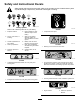
Safety and Instructional Decals Safety decals and instructions are easily visible to the operator and are located near any area of potential danger. Replace any decal that is damaged or missing. decalbatterysymbols Battery Symbols Some or all of these symbols are on your battery. 1. Explosion hazard 6. Keep bystanders a safe distance away from the battery. 2. No fire, open flame, or smoking 7. Wear eye protection; explosive gases can cause blindness and other injuries. 3.
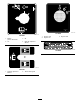
decal117-3276 117-3276 1. Engine coolant under pressure 3. Warning—do not touch the hot surface. 2. Explosion hazard—read the Operator's Manual. 4. Warning—read the Operator's Manual. decal130-7637 130-7637 decal120-0625 120-0625 1. Pinch point, hand—keep hands away. 1. Blinking light—engine-coolant temperature 6. Engine start 2. Steady light—engine-oil pressure 7. Parking brake disengaged 3. Blinking light—glow plug 8. Traction neutral 4. Steady light—battery warning 9.
decal137-9030 137-9030 decal131-8026 131-8026 1. Engine—stop 3. Engine—start 2. Engine—run 1. Battery power—disconnect 3. Off 2. On 4. Read the Operator's Manual. decal133-8056 133-8056 decal136-5750 136-5750 1. Read the Operator's Manual. 2.
decal131-0597 131-0597 decal131-0708 131-0708 3. Move rearward 4. Turn left 1. Move forward 2.
decal131-0710 131-0710 1. Warning—read the Operator's Manual. 7. Cutting/severing hazard of hand or foot—wait for all moving parts to stop before servicing; keep away from moving parts; keep all guards and shields in place. 2. Warning—receive training before operating the machine. 8. Explosion hazard; electrocution hazard—call the local utilities hotline before beginning work in an area. 3. Warning—wear hearing protection. 9.
Controls Product Overview Become familiar with all the controls (Figure 4) before you start the engine and operate the traction unit. Control Panel g259644 Figure 4 1. Message display 2. Power socket 3. Reference bar 4. Plug g031208 5. Auxiliary hydraulics lever 6. Throttle lever 7. Key switch 8. Traction control 9. Loader-arm/attachment-tilt lever 10. Loader lock Key Switch The key switch, used to start and shut off the engine, has 3 positions: OFF, RUN, and START .
Traction Control • To turn right, rotate the traction control clockwise (Figure 8). g259646 Figure 5 g259649 Figure 8 1. Reference bar 2. Traction control • To turn left, rotate the traction control • To move forward, move the traction control forward counterclockwise (Figure 9). (Figure 6). g259648 Figure 9 g259645 Figure 6 • To stop the machine, release the traction control • To move rearward, move the traction control (Figure 5). rearward (Figure 7).
Loader Arm/Attachment-Tilt Lever Loader-Valve Lock • To tilt the attachment forward, slowly move the The loader-valve lock secures the loader arm/attachment-tilt lever so that you cannot push it forward. This helps to ensure that no one accidentally lowers the loader arms during maintenance. Secure the loader arms with the lock anytime you need to shut off the machine with the loader arms raised. lever to the right (Figure 10).
Auxiliary-Hydraulics Lever Parking-Brake Lever • To operate a hydraulic attachment in the forward • To engage the parking brake, rotate the lever to direction, move the auxiliary-hydraulics lever forward (Figure 12). left (Figure 14). Note: The traction unit may roll slightly before the • To operate a hydraulic attachment in the reverse brakes engage in the drive sprocket. direction, move the auxiliary-hydraulics lever rearward (Figure 12).
Message Display Battery-Charge Light If the battery charge becomes too low, the light on the right illuminates steadily (Figure 18). If this happens, shut off the engine and charge or replace the battery. Refer to Servicing the Battery (page 34). Engine-Coolant-Temperature Light If the engine coolant becomes too hot, the light on the left flashes and the horn sounds (Figure 15).
Specifications Operation Note: Specifications and design are subject to Note: Determine the left and right sides of the machine from the normal operating position. change without notice.
Filling the Fuel Tanks • Do not add or drain fuel in an enclosed space. • Do not store the machine or fuel container where Fuel tank capacity: 41 L (11 US gallons) there is an open flame, spark, or pilot light, such as on a water heater or other appliance. Fill the fuel tanks as shown in Figure 23. • If you spill fuel, do not attempt to start the engine; Note: The fuel-tank caps click when you close them avoid creating any source of ignition until the fuel vapors have dissipated. securely.
During Operation • Slow down and use caution when making turns During Operation Safety • Stop the attachment when you are not working. • Stop the machine, turn off the engine, remove and crossing roads and sidewalks. Watch for traffic. General Safety the key, and inspect the machine if you strike an object. Make any necessary repairs before resuming operation. • Do not carry a load with the arms raised. Always • • • • • • • • • • • • • carry loads close to the ground.
Starting the Engine use common sense and good judgment when performing this survey. 1. Ensure that the battery-disconnect switch is in the ON position. 2. Ensure that the auxiliary-hydraulics lever and traction-control are in the NEUTRAL position. 3. Move the throttle lever midway between the SLOW and FAST positions. slowly and keep the heavy end of the machine uphill. 4. Insert the key into the key switch and turn it to the ON position. • Keep all movements on slopes slow and gradual. 5.
Shutting Off the Engine 1. Park the machine on a level surface, engage the parking brake (if equipped), and lower the loader arms. 2. Ensure that the auxiliary hydraulics lever is in the NEUTRAL position. 3. Move the throttle lever to the SLOW position. 4. If the engine has been working hard or is hot, let it idle for a minute before turning the key switch to the OFF position. g003710 Figure 24 Note: This helps to cool the engine before you shut it off.
Connecting the Hydraulic Hoses WARNING Hydraulic fluid escaping under pressure can penetrate skin and cause injury. Fluid injected into the skin must be surgically removed within a few hours by a doctor familiar with this form of injury; otherwise, gangrene may result. • Ensure that all hydraulic-fluid hoses and lines are in good condition and all hydraulic connections and fittings are tight before applying pressure to the hydraulic system.
Removing an Attachment 1. Park the machine on a level surface. 2. Lower the attachment to the ground. 3. Shut off the engine and remove the key. 4. Disengage the quick-attach pins by turning them to the outside. 5. If the attachment uses hydraulics, move the auxiliary-hydraulics lever forward, backward, and back to the NEUTRAL position to relieve pressure at the hydraulic couplers. 6. If the attachment uses hydraulics, slide the collars back on the hydraulic couplers and disconnect them. 4.
Loading the Machine Selecting a Trailer WARNING WARNING Loading a machine onto a trailer or truck increases the possibility of tip-over and could cause serious injury or death (Figure 27). Loading a machine onto a trailer or truck increases the possibility of tip-over and could cause serious injury or death. • Use only a full-width ramp; do not use individual ramps for each side of the machine. • Use extreme caution when operating a machine on a ramp.
g031331 Figure 29 1. Tie-down loops Unloading the Machine 1. Lower the ramp (Figure 28). 2. Unload the machine from the trailer with the heavy end up the ramp, carrying loads low (Figure 30). • If the machine has a full load-carrying attachment (e.g., bucket or adjustable forks) or a non-load-carrying attachment (e.g., stump grinder), back it down the ramp. • If the machine has an empty load-carrying attachment or no attachment, drive it forward down the ramp. g204458 Figure 30 1.
Maintenance Note: Determine the left and right sides of the machine from the normal operating position. Important: Refer to your engine owner’s manual for additional maintenance procedures. CAUTION If you leave the key in the switch, someone could accidently start the engine and seriously injure you or other bystanders. Remove the key from the switch before you perform any maintenance.
Maintenance Service Interval Yearly Yearly or before storage Every 2 years Maintenance Procedure • Change the engine coolant (Authorized Service Dealer only). • Change the engine coolant. • Check and adjust the track tension. • Touch up chipped paint. • Drain and clean the fuel tank(s)—Authorized Service Dealer only. • Replace all moving hydraulic hoses. Pre-Maintenance Procedures Using the Cylinder Locks WARNING The loader arms may lower when in the raised position, crushing anyone under them.
Removing and Storing the Cylinder Locks Important: Remove the cylinder locks from the rods and fully secure them in the storage position before operating the machine. 2. Turn the hood latch clockwise (Figure 32). 3. Lift up on the handles and swing the hood up (Figure 32). 4. Secure the prop rod. Closing the Hood 1. Start the engine. 2. Raise the loader arms to the fully raised position. 3. Shut off the engine and remove the key. 4. Remove the pins securing the cylinder locks. 5.
Removing the Front Cover Removing the Side Screens 1. Open the hood and secure the hood prop. 2. Slide the side screens (Figure 35) up and out of the slots in the front screen and frame. 1. Remove the 2 upper bolts (3/8 x 1 inch), 2 washers, and 2 lower bolts (5/16 x 5/8 inch) from the front cover. 2. Remove the front cover. g030720 Figure 35 Loader arms not shown for clarity g204032 1. Side screen Figure 37 Removing the Front Screen 1. Open the hood and secure the hood prop. 2.
Lubrication Greasing the Machine Service Interval: Before each use or daily (Grease immediately after every washing.) Grease Type: General-purpose grease. 1. Park the machine on a level surface, engage the parking brake, and lower the loader arms. 2. Shut off the engine and remove the key. 3. Clean the grease fittings with a rag. 4. g004209 Figure 39 Connect a grease gun to each fitting (Figure 38, Figure 39, and Figure 40). Note: Raise the loader arms before greasing the fittings in Figure 40.
Engine Maintenance Engine Safety • Shut off the engine before checking the oil or adding oil to the crankcase. • Do not change the engine governor setting or overspeed the engine. • Keep your hands, feet, face, clothing, and other body parts away from the muffler and other hot surfaces. g031236 Figure 41 Servicing the Air Cleaner Service Interval: Before each use or daily—Check the air-filter-service indicator.
Important: Do not press on the soft inside area of the filter. 4. Install the air-cleaner cover with the dust cap oriented downward and secure the latches (Figure 41). 5. Close the hood. Servicing the Engine Oil Service Interval: Before each use or daily—Check the engine-oil level. g029940 Figure 43 After the first 50 hours—Change the engine oil and filter. 1. Oil-fill cap Every 100 hours—Change the engine oil. (Service more frequently if conditions are extremely dusty or sandy.) 5. 2.
4. Engage the parking brake, shut off the engine, and remove the key. 5. Drain the oil beneath the platform (Figure 45). Changing the Oil Filter CAUTION Components will be hot if the machine has been running. If you touch hot components, you may be burned. Use care to avoid touching hot components while changing the oil and/or filter. 1. Raise the loader arms and secure with the cylinder locks; refer to Installing the Cylinder Locks (page 25). 2.
Replacing the Fuel Filter Canister and In-Line Filter Fuel System Maintenance Service Interval: Every 400 hours DANGER 1. In certain conditions, fuel is extremely flammable and highly explosive. A fire or explosion from fuel can burn you and others and can damage property. Park the machine on a level surface, engage the parking brake, and lower the loader arms. 2. Shut off the engine and remove the key. 3. Open the rear-access cover; refer to Opening the Rear-Access Cover (page 26).
Checking the Fuel Lines and Connections Service Interval: Every 400 hours/Yearly (whichever comes first) Inspect the fuel lines and connections for deterioration, damage, or loose connections. Tighten any loose connections and contact your Authorized Service Dealer for assistance in fixing damaged fuel lines.
Electrical System Maintenance Electrical System Safety • Disconnect the battery before repairing the machine. Disconnect the negative terminal first and the positive last. Connect the positive terminal first and the negative last. • Charge the battery in an open, well-ventilated area, away from sparks and flames. Unplug the charger before connecting or disconnecting the battery. Wear protective clothing and use insulated tools. • Battery acid is poisonous and can cause burns.
Removing the Battery 1. Park the machine on a level surface, engage the parking brake, and lower the loader arms. 2. Shut off the engine and remove the key. 3. Remove the battery as shown in Figure 49. g204573 Figure 49 Charging the Battery WARNING Charging the battery produces gasses that can explode. Never smoke near the battery and keep sparks and flames away from battery. Important: Always keep the battery fully charged (1.265 specific gravity).
Cleaning the Battery 4. Note: Keep the terminals and the entire battery case clean, because a dirty battery discharges slowly. Wash the entire case with a solution of baking soda and water. 5. Rinse the battery with clear water. 1. Park the machine on a level surface, engage the parking brake (if equipped), and lower the loader arms. 6. Coat the battery posts and cable connectors with Grafo 112X (skin-over) grease (Toro Part No. 505-47) or petroleum jelly to prevent corrosion. 2.
Jump-Starting the Machine WARNING Contact with hot surfaces may cause personal injury. Keep your hands, feet, face, clothing and other body parts away the muffler and other hot surfaces. WARNING Jump-starting the battery can produce gasses that can explode. Do not smoke near the battery, and keep sparks and flames away from battery. 1. Open the hood, secure the prop rod, and remove the left side screen. 2. Remove the cover from the jump post (Figure 52). g033902 Figure 52 1. Jump post 3.
Servicing the Fuses Drive System Maintenance The electrical system is protected by fuses. It requires no maintenance; however, if a fuse blows, check the component/circuit for a malfunction or a short. Figure 53 illustrates the fuse block and identifies the fuse positions. Servicing the Tracks Service Interval: After the first 8 hours—Check and adjust the track tension. Every 50 hours—Check and adjust the track tension. Before each use or daily—Clean the tracks.
Adjusting the Track Tension 5. Machines with Narrow Tracks Using a 1/2 inch drive ratchet, turn the tensioning screw until the track deflection is 12.7 mm (1/2 inch) as shown in Figure 56. Note: Turning the screw counter-clockwise tightens the track; turning the screw clockwise loosens the track. Lift/support 1 side of the machine and using the weight of the track, verify that the gap between the bottom of the lip of the road wheel and the track is 12.7 mm (1/2 inch) as shown in Figure 56.
Replacing the Tracks Machines with Narrow-Width Tracks Replace the tracks when they are badly worn. 1. Remove any attachments. 2. Park the machine on a level surface, ensuring that only 1 sprocket half is engaged with the track (Figure 60). g029758 Figure 59 1. Tension tube 3. Tensioning screw 2. Locking bolt 4. Using a 1/2 inch drive ratchet, turn the tensioning screw until the tension block aligns with the green guide on the decal or is 1.
g259736 Figure 63 g258146 12. Figure 61 1. Sprocket 4. Ratchet (1/2 inch) 2. Track 5. Road wheel (5) 13. 14. 3. Front wheel 9. 15. Remove the 3 bolts securing the sprocket half that is not engaged with the track (Figure 61). 16. 17. Engage the parking brake, shut off the engine, and remove the key. Remove the track from the track frame. Wrap the new track around the front wheel (Figure 61). Push the track under and between the road wheels and wrap it around the frame (Figure 61).
24. Drive the machine, then park the machine on a level surface, engage the parking brake, shut off the engine, and remove the key. 25. Verify that the track deflection is 12.7 mm (1/2 inch) as shown in Figure 56. Machines with Wide-Width Tracks Replace the tracks when they are badly worn. 1. Park the machine on a level surface, engage the parking brake, and lower the loader arms. 2. Shut off the engine and remove the key. 3. Lift/support the side of the unit to be worked on so that the track is 7.
Cooling System Maintenance Cooling System Safety • Swallowing engine coolant can cause poisoning; keep out of reach from children and pets. • Discharge of hot, pressurized coolant or touching a hot radiator and surrounding parts can cause severe burns. g203963 Figure 67 1. Tension nut 2. Tension screw 16. Align the closest notch in the tension screw to the locking bolt hole and secure the screw with the locking bolt and nut. 17. Torque the rear bolt to 108 to 122 N∙m (80 to 90 ft-lb). 18.
Brake Maintenance Testing the Parking Brake Service Interval: Before each use or daily g029314 Figure 68 1. Expansion tank 2. Full mark 4. If the coolant level is low, remove the expansion tank cap and add a 50/50 mixture of water and permanent ethylene-glycol antifreeze. Important: Do not overfill the expansion tank. 5. Install the expansion-tank cap. Changing the Engine Coolant Service Interval: Yearly Have an Authorized Service Dealer change the engine coolant yearly.
Controls System Maintenance Hydraulic System Maintenance Adjusting the Controls Hydraulic System Safety • Seek immediate medical attention if fluid is injected The factory adjusts the controls before shipping the machine. However, after many hours of use, you may need to adjust the traction control alignment, the NEUTRAL position of the traction control, and the tracking of the traction control in the full forward position.
lowered or at the lower notch while the arms are raised. Industry Standards API GL-4, AGCO Powerfluid 821 XL, Ford New Holland FNHA-2-C-201.00, Kubota UDT, John Deere J20C, Vickers 35VQ25 and Volvo WB-101/BM Note: Many hydraulic fluids are almost colorless, making it difficult to spot leaks. A red dye additive for the hydraulic system fluid is available in 20 ml (2/3 fl oz) bottles. One bottle is sufficient for 15 to 22 L (4 to 6 US gallons) of hydraulic fluid. Order Part No.
6. Remove the hydraulic-tank cap and dipstick (Figure 72). g029729 Figure 72 1. Filler neck 7. 2. Dipstick Place a large drain pain capable of holding 57 L (15 US gallons) under the drain plug on the front of the machine (Figure 73). g205342 Figure 71 5. Clean up any spilled fluid. 6. Start the engine and let it run for about 2 minutes to purge air from the system. 7. Shut off the engine and check for leaks. 8.
Cleaning the Chassis Cleaning Service Interval: Every 100 hours—Check for dirt buildup in the chassis. Removing Debris Over time, the chassis under the engine collects dirt and debris that must be removed. Using a flashlight, open the hood and inspect the area under the engine regularly. When the debris is 2.5 to 5 cm (1 to 2 inches) deep, clean the chassis.
Storage Storage Safety • Shut off the engine, remove the key, wait for all moving parts to stop, and allow the machine to cool before storing it. • Do not store the machine or fuel near flames. Storage 1. Park the machine on a level surface, engage the parking brake, and lower the loader arms. 2. Shut off the engine and remove the key. 3. Remove dirt and grime from the entire machine. Important: You can wash the machine with mild detergent and water. Do not pressure-wash the machine.
Troubleshooting Problem The starter does not crank. Possible Cause 1. The electrical connections are corroded or loose. 1. Check the electrical connections for good contact. 2. A fuse is blown or loose. 3. The battery is discharged. 4. The relay or switch is damaged. 2. Correct or replace the fuse. 3. Charge the battery or replace it. 4. Contact your Authorized Service Dealer. 5. Contact your Authorized Service Dealer. 6. Contact your Authorized Service Dealer. 7.
Problem The engine starts but does not keep running. Possible Cause 1. The fuel-tank vent is restricted. 1. Loosen the cap. If the engine runs with the cap loosened, replace the cap. 2. Dirt or water is in the fuel system. 2. Drain and flush the fuel system; add fresh fuel. 3. Replace the fuel filter. 4. Bleed the nozzles and check for air leaks at fuel hose connections and fittings between the fuel tank and engine. 5. Drain the fuel system and replace the fuel filter.
Problem The engine overheats. Possible Cause 1. More coolant is needed. 1. Check and add coolant. 2. There is restricted air flow to the radiator. 3. The crankcase-oil level is incorrect. 4. The engine load is excessive. 2. Inspect and clean the radiator screen with every use. 3. Fill or drain to the Full mark. 4. Reduce the load; use a lower ground speed. 5. Drain and flush the fuel system; add fresh fuel. 6. Contact your Authorized Service Dealer. 7. Contact your Authorized Service Dealer. 8.
Problem Exhaust produces excessive white smoke. Possible Cause 1. The key was turned to the START position before the glow-plug light turned off. 1. Turn the key to the RUN position and allow the glow-plug light to turn off before starting the engine. 2. The engine temperature is low. 3. The glow plugs are inoperative. 4. The injection-pump timing is incorrect. 2. Check the thermostat. 3. Check the fuse, glow plugs, and wiring. 4. Contact your Authorized Service Dealer. 5.
Schematics g240932 Electrical Schematic (Rev.
g260360 Hydraulic Schematic (Rev.
Notes:
Notes:
Notes:
European Privacy Notice The Information Toro Collects Toro Warranty Company (Toro) respects your privacy. In order to process your warranty claim and contact you in the event of a product recall, we ask you to share certain personal information with us, either directly or through your local Toro company or dealer. The Toro warranty system is hosted on servers located within the United States where privacy law may not provide the same protection as applies in your country.
California Proposition 65 Warning Information What is this warning? You may see a product for sale that has a warning label like the following: WARNING: Cancer and Reproductive Harm—www.p65Warnings.ca.gov. What is Prop 65? Prop 65 applies to any company operating in California, selling products in California, or manufacturing products that may be sold in or brought into California.