
Operator's Manual


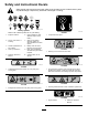


ProductOverview
g031208
g259625
Figure3
1.Hood
7.Tie-down/liftloop
2.Auxiliaryhydraulic
couplers
8.Fuelgauge
3.Mountplate
9.Controlpanel
4.Track10.Auxiliaryhydraulicslock
switch
5.Loaderarm
11.Operatorplatform
6.Liftcylinder
12.Parkingbrake
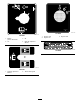
Controls
Becomefamiliarwithallthecontrols(Figure4)before
youstarttheengineandoperatethetractionunit.
ControlPanel
g259644
Figure4
1.Messagedisplay6.Throttlelever
2.Powersocket7.Keyswitch
3.Referencebar
8.Tractioncontrol
4.Plug
9.Loader-arm/attachment-tilt
lever
5.Auxiliaryhydraulicslever
10.Loaderlock
KeySwitch
Thekeyswitch,usedtostartandshutofftheengine,
has3positions:OFF,RUN,andSTART.Referto
StartingtheEngine(page18).
ThrottleLever
Movethecontrolforwardtoincreasetheenginespeed
andrearwardtodecreasespeed.
ReferenceBar
Whendrivingthetractionunit,usethereferencebar
asahandleandaleveragepointforcontrollingthe
tractioncontrolandtheauxiliary-hydraulicslever.T o
ensuresmooth,controlledoperation,donottake
yourhandsoffthereferencebarswhileoperatingthe
machine.
10