
Operator's Manual

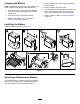


AdjustingtheTrackTension
MachineswithNarrowTracks
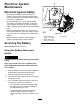
Lift/support1sideofthemachineandusingtheweight
ofthetrack,verifythatthegapbetweenthebottom
ofthelipoftheroadwheelandthetrackis12.7mm
(1/2inch)asshowninFigure56.Ifitisnot,adjustthe
tracktensionusingthefollowingprocedure.
g257979
Figure56
1.Roadwheel
1.Parkthemachineonalevelsurface,engagethe
parkingbrake,andlowertheloaderarms.
2.Shutofftheengineandremovethekey.
3.Raisethesideofthemachinethatyouare
adjustingsothatthetrackisofftheground.
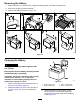
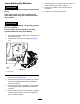
4.Removethelockingbolt,spacer,andnut(Figure
57).
g257903
Figure57
1.Lockingbolt
3.Spacer
2.Tensioningscrew4.Nut
5.Usinga1/2inchdriveratchet,turnthetensioning
screwuntilthetrackdeectionis12.7mm(1/2
inch)asshowninFigure56.
Note:Turningthescrewcounter-clockwise
tightensthetrack;turningthescrewclockwise
loosensthetrack.
6.Aligntheclosestnotchinthetensionscrewto
thelocking-boltholeandsecurethescrewwith
thelockingboltandnut(Figure57).
7.Repeattheprocedurefortheothertrack.
8.Drivethemachine,thenparkthemachineona
levelsurface,engagetheparkingbrake,shutoff
theengine,andremovethekey.
9.Verifythatthetrackdeectionis12.7mm(1/2
inch)asshowninFigure56.Adjustifnecessary.
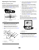
MachineswithWideTracks
Verifythatthetensionblockisalignedwiththegreen
guideonthedecalorthattheblockis1.3cm(1/2inch)
awayfromtherearofthetensiontubeslot(Figure58).
g203962
Figure58
1.Greenguideondecal
2.Tensionblock
1.Parkthemachineonalevelsurface,engagethe
parkingbrake,andlowertheloaderarms.
2.Shutofftheengineandremovethekey.
3.Removethelockingbolt,spacer,andnut(Figure
59).
39