
Operator's Manual


g259736
Figure63
12.Engagetheparkingbrake,shutofftheengine,
andremovethekey.
13.Removethetrackfromthetrackframe,drive
hub,thenfrontwheel.
14.Wrapthenewtrackaroundthefrontwheel,then
wrapthetrackaroundthedrivehubontheside
withoutthesprocket(Figure61).
15.Pushthetrackunderandbetweentheroad
wheelsandwrapitaroundtheframe(Figure61).
16.Starttheengineanddisengagetheparking
brake.
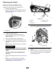
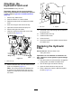
17.Movethetractioncontrolforwarduntilthedrive
sprockethalfengageswiththetrack(Figure64).
g259737
Figure64
18.Engagetheparkingbrake,shutofftheengine,
andremovethekey.
19.Applythread-lockingcompoundtotheboltsof
thedrivesprockethalfthatyouremovedand
installthesprockethalf(Figure62).Torquethe
boltsto95to115N∙m(70to85ft-lb).
20.Usinga1/2inchdriveratchet,turnthetensioning
screwcounter-clockwiseuntilthetrackdeection
is12.7mm(1/2inch)asshowninFigure56.
21.Aligntheclosestnotchinthetensionscrewto
thelockingboltholeandsecurethescrewwith
thelockingbolt,spacer,andnut.
22.Lowerthemachinetotheground.
23.Repeattheproceduretoreplacetheothertrack.
24.Drivethemachine,thenparkthemachineona
levelsurface,engagetheparkingbrake,shutoff
theengine,andremovethekey.
25.Verifythatthetrackdeectionis12.7mm(1/2
inch)asshowninFigure56.
MachineswithWide-WidthTracks
Replacethetrackswhentheyarebadlyworn.
1.Parkthemachineonalevelsurface,engagethe
parkingbrake,andlowertheloaderarms.
2.Shutofftheengineandremovethekey.
3.Lift/supportthesideoftheunittobeworkedon
sothatthetrackis7.6to10cm(3to4inches)
offtheground.
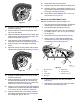
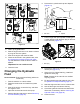
4.Removethelockingboltandnut(Figure59).
5.Usinga1/2-inchdriveratchet,releasethe
drivetensionbyturningthetensioningscrew
clockwise(Figure59andFigure65).
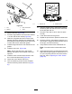
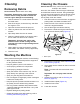
g029759
Figure65
1.Drivesprocket5.Roadwheel
2.Track6.Pivottensioner
3.Frontwheel
7.Ratchet(1/2inch)
4.Rearbolt
6.Loosentherearbolt,nearthedrivewheel
(Figure65).
7.Removethenutsecuringtheouterfrontwheel
andremovethewheel(Figure66).
43