Form No. 3353-732 Rev A TX 413 Compact Utility Loader Model No. 22330—250000001 and Up Operator’s Manual Register your product at www.Toro.
Warning Keep this engine Owner’s Manual with your unit. Should this engine Owner’s Manual become damaged or illegible, replace immediately. Replacements may be ordered through the engine manufacturer. Before Operating . . . . . . . . . . . . . . . . . . . . . . . . . . . . Adding Fuel . . . . . . . . . . . . . . . . . . . . . . . . . . . . . Checking the Oil Level . . . . . . . . . . . . . . . . . . . . Removing Debris from the Traction Unit . . . . . . Checking the Hydraulic Fluid . . . . . . . . . . . .
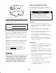
Safe Operating Practices This product is capable of amputating hands and feet. Always follow all safety instructions to avoid serious injury or death. 1 Warning Engine exhaust contains carbon monoxide, an odorless, deadly poison that can kill you. m–7487 Figure 1 Do not run the engine indoors or in an enclosed area. 1. Model and serial number plate For your convenience, write the product model and serial numbers in the space below. Training • Read the Operator’s Manual and other training material.
• Do not exceed the rated operating capacity, as the traction unit may become unstable which may result in loss of control. • Never refuel or drain the machine indoors. • Check that the operator’s presence controls, safety switches, and shields are attached and functioning properly. Do not operate unless they are functioning properly. • Do not carry a load with the arm raised. Always carry loads close to the ground.
• Keep all parts in good working condition and all hardware tightened. Replace all worn or damaged decals. • Use only Toro-approved attachments. Attachments can change the stability and the operating characteristics of the traction unit. Warranty may be voided if used with unapproved attachments. • Keep all movements on slopes slow and gradual. Do not make sudden changes in speed or direction.
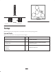
Slope Chart Note: This page may be copied for personal use only.
Safety and Instruction Decals Safety decals and instructions are easily visible to the operator and are located near any area of potential danger. Replace any decal that is damaged or lost.
104-2838 106-9514 93-9084 1. Lift point 2. Tie-down point Setup Note: Determine the left and right sides of the machine from the normal operating position. Loose Parts Note: Use the chart below to verify all parts have been shipped. Description Qty. Battery post bolt 2 Battery post nut 2 Engine Manual 1 Training video 1 Hydraulic filter 1 Ignition key 2 Hood key 2 Plug wrench 1 8 Use Activate the battery. Read/watch to learn important information about your product.
Activating the Battery 1 Warning 2 Battery posts, terminals, and related accessories contain lead and lead compounds, chemicals known to the State of California to cause cancer and reproductive harm. Wash hands after handling. 3 1262 Figure 3 The traction unit is shipped with a dry battery. Purchase bulk electrolyte with 1.260 specific gravity from a local battery supply outlet. 1. Filler caps 2. Electrolyte 3. Lower part of the tube 1.
Important Do not allow the battery posts to touch the frame or hydraulic lines or it may cause sparks. 9. Secure the battery in chassis with the clamp, bolts, and nuts removed previously (Fig. 2). 10. Using the bolt and nut supplied with the battery, connect the positive (red) cable to the positive (+) battery post (Fig. 2). Slide the rubber cover over the battery post. 11. Using the bolt and nut supplied with the battery, connect the negative (black) cable to the negative (–) battery post (Fig. 2).
Stability Data The following tables list the maximum slope recommended for the traction unit in the positions listed in the tables. Slopes over the listed degree may cause the traction unit to become unstable. The data in the tables assume that the loader arm are fully lowered; raised arm may affect the stability. In each attachment manual is a set of three stability ratings, one for each hill position.
Before Operating Using Stabilizer/Conditioner Use a fuel stabilizer/conditioner in the traction unit to provide the following benefits: Before operating, check the fuel and oil level, and remove debris from the traction unit. Also, ensure that the area is clear of people and debris. You should also know and have marked the locations of all utility lines. • Keeps gasoline fresh during storage of 90 days or less. For longer storage it is recommended that the fuel tank be drained.
7. If there is no or little oil on the dipstick, add 10w30 engine oil to the filler hole until it comes to the edge of the filler hole (Fig. 7 and 8). Important This space in the tank allows gasoline to expand. Do not fill the fuel tank completely full (Fig. 6). 5. Install the fuel tank cap securely. 8. Replace the dipstick. 6. Wipe up any gasoline that may have spilled. Removing Debris from the Traction Unit Checking the Oil Level 1.
1 1 m–7466 m–7467 Figure 10 Figure 9 1. Filler neck cap 1. Dipstick 6. Check the fluid level on the dipstick (Fig. 10). 7. If the level is low, add enough fluid to raise it to the proper level. The fluid level should be between the marks on the dipstick. 8. Install the cap on the filler neck. Operation Traction Unit Overview Figure 11 contains a front and back view of the traction unit. Familiarize yourself with all of the traction unit components listed in Figure 11.
Controls Traction Control Become familiar with all the controls (Fig. 12) before you start the engine and operate the traction unit. To move forward, move the traction control forward. To move rearward, move the traction control rearward (Fig. 13). 5 6 7 To turn, rotate the traction control in the desired direction (Fig. 13). 3 The farther you move the traction control in any direction, the faster the traction unit will move in that direction. 2 To stop, release the traction control.
Loader Arm/Attachment Tilt Lever If you release the lever while in either the forward position or upper reverse position, the lever will automatically return to the neutral position (Fig. 15). To tilt the attachment forward, slowly move the lever to the right (Fig. 14). To tilt the attachment rearward, slowly move the lever to the left (Fig. 14). 1 To lower the loader arm, slowly move the lever forward (Fig. 14). To raise the loader arm, slowly move the lever rearward (Fig. 14).
The Fuel Valve Lever Hour Meter Important Use the cylinder lock when raising the loader arm to access the fuel valve lever. Refer to the Using the Cylinder Lock section on page 19. When the engine is off, the hour meter displays the number of hours of operation that have been logged on the traction unit. The fuel valve lever opens and closes the passage between the fuel tank and the carburetor. The fuel valve lever is shipped from the factory in the open position.
B A A C C B D E D Figure 21 2. Lower the loader arm (Fig. 21, B). Figure 20 3. Turn the ignition key to the stop position (Fig. 21, C). Note: If the engine has been working hard or is hot, let it idle for a minute before turning the ignition key off. This helps cool the engine before it is stopped. In an emergency, the engine may be stopped immediately. 3. Move the choke lever to the On position (Fig 20, B). Note: A warm or hot engine may not require choking. 4.
3. Using a wrench, turn the tow valves (Fig. 22) on the hydraulic pumps twice counter-clockwise. 1 2 m–7460 Figure 23 1. Cylinder lock 2. Clevis and hairpin cotter 5. Place the cylinder lock over the cylinder rod and secure it with the clevis pin and hairpin cotter (Fig. 24). 1 m–7576 4 Figure 22 3 4. Close the hood and tow the traction unit as required. 2 5. When the traction unit has been repaired, close the tow valves before operating it. m–7461 Figure 24 Using the Cylinder Lock 1.
6. Lower the loader arm. Warning Using Attachments If you do not fully seat the quick attach pins through the attachment mount plate, the attachment could fall off of the traction unit, crushing you or bystanders. Connecting an Attachment Important Use only Toro-approved, TX 413 attachments. Attachments can change the stability and the operating characteristics of the traction unit. The warranty of the traction unit may be voided if used with unapproved attachments.
6. Push the attachment male coupler into the female coupler on the traction unit (Fig. 27). 7. Push the attachment female coupler onto the male connector on the traction unit (Fig. 28). m–7489 Figure 27 m–7490 Figure 28 Note: When you connect the attachment male coupler first, you will relieve any pressure build up in the attachment. 8. Confirm that the connection is secure by pulling on the hoses. Warning 9. Move the auxiliary hydraulics lever to neutral. 10.
5. If the attachment uses hydraulics, slide the collar back on the hydraulic couplers and disconnect them. 6. Install the protective covers onto the hydraulic couplers on the traction unit. 7. Start the engine, tilt the mount plate forward, and back the traction unit away from the attachment. Securing the Traction Unit for Transport Important roadways. Do not operate or drive the traction unit on Important When transporting the traction unit on a trailer, always use the following procedure: 1.
Maintenance Recommended Maintenance Schedule Important Refer to your engine operator’s manual for additional maintenance procedures.
Caution If you leave the key in the ignition switch, someone could accidently start the engine and seriously injure you or other bystanders. Remove the key from the ignition and disconnect the wire from the spark plug before you do any maintenance. Set the wire aside so that it does not accidentally contact the spark plug. Accessing the Engine and Internal Components Closing the Hood Lower the hood and secure it by pushing down on the front of the hood until it locks in place.
Adjusting the Controls 5. Adjust the traction control so that it rest flush against the reference bar when it is pulled straight back (Fig. 37 and 38). The factory adjusts the controls before shipping the traction unit. However, after many hours of use, you may need to adjust the traction control alignment, the neutral position of the traction control, and the tracking of the traction control in the full forward position.
Servicing the Air Cleaner 5. If the left track moves, lengthen or shorten the right traction rod until the track stops moving. Foam Pre-filter: Clean every 50 operating hours. 6. If the right track moves, lengthen or shorten the left traction rod until the track stops moving. Paper Filter: Clean every 50 operating hours. Replace after every 100 operating hours. 7. Tighten the jam nuts. Note: Service the air cleaner more frequently if operating conditions are extremely dusty or sandy. 8.
2. Place the filter assembly onto the air cleaner base and secure it with a wingnut (Fig. 42). 6. Carefully slide the foam filter off of the paper filter (Fig. 43). 3. Install the air cleaner cover and secure it with the wingnut (Fig. 42). 2 4. Close the hood. Servicing the Engine Oil 1 Change oil after the first 20 operating hours and then every 100 operating hours thereafter. m–7458 Note: Change oil more frequently when operating conditions are extremely dusty or sandy. Figure 43 1.
3. Using a water hose or pressure washer, remove dirt from each track system. 4. Remove the drain plug (Fig. 44). Important Ensure that you use high-pressure water to wash only the track area. Do not use a high-pressure washer to clean the rest of the traction unit. High-pressure washing can damage the electrical system and hydraulic valves or deplete grease. 1 Important Ensure that you fully clean the road wheels, the tension wheel, and the drive sprocket (Fig. 46).
3. Remove the locking bolt and nut (Fig. 48). 1 3 4 8 4 3 2 1 5 6 m–6782 m–7574 2 Figure 49 Figure 48 1. Locking bolt 2. Tensioning screw 7 1. 2. 3. 4. 3. Tension tube 4. Tension wheel 4. Using a 1/2 inch drive socket (Fig. 49), turn the tensioning screw counter-clockwise until the distance between the tension nut and the back of the tension tube (Fig. 47) is 2-3/4 inches (7 cm). Track 1/2 inch socket Tension wheel Fork tube 5. 6. 7. 8.
Maintaining the Road Wheels 5. Ensure that the road wheel turns smoothly on the bearing. If it is frozen, replace the road wheel as described in the Road Wheel Kit Installation Instructions or contact your Authorized Service Dealer for repair. Check and grease the road wheels every 250 operating hours or yearly. 1. Remove the tracks; refer to Replacing the Tracks, page 29. 6. Place the greased road wheel cap over the bolt head (Fig 51). 2.
Installing the Spark Plug Note: There is a hole in the front panel through which you can gain access to the spark plug with a socket (Fig. 53). 1. Thread the spark plug into the spark plug hole. 2. Tighten the spark plug until it compresses the metal washer and then seat it as follows: • If you are installing a used spark plug, tighten it another 1/8 to 1/4 turn. • If you are installing a new spark plug, tighten it another 1/2 turn. Important A loose spark plug can overheat and damage the engine.
m–7481 Figure 56 m–7485 Figure 60 m–7482 Figure 57 m–7486 Figure 61 m–7483 Figure 58 m–7487 Figure 62 m–7484 Figure 59 32
Draining the Fuel Tank 7. Install the replacement hydraulic filter onto the filter adapter (Fig. 63). Tighten it clockwise until the rubber gasket contacts the filter adapter, then tighten the filter an additional 3/4 turn. Danger In certain conditions, gasoline is extremely flammable and highly explosive. A fire or explosion from gasoline can burn you and others and can damage property. • Drain gasoline from the fuel tank when the engine is cold. Do this outdoors in an open area.
Note: Dispose of the used oil at a certified recycling center. 4. Allow the traction unit to cool completely. 5. Remove the hydraulic tank cap and dipstick (Fig. 64 and 65). 9. Fill the hydraulic tank with approximately 10 US gallons (37.8 l) of 10W-30 detergent, diesel engine oil (API service CH-4 or higher); refer to Checking Hydraulic Fluid, page 13. 10. Start the engine and let it run for a few minutes. 1 11. Stop the engine. 12.
Charging the Battery Important The following procedures apply when servicing a (dry) battery that has replaced the original battery. The original (wet) battery does not require service. Important Always keep the battery fully charged (1.260 specific gravity). This is especially important to prevent battery damage when the temperature is below 32°F (0°C). Check the electrolyte level in the battery every 100 hours. Always keep the battery clean and fully charged.
Storage Important Do not store stabilizer/conditioned gasoline over 90 days. 1. Lower the loader arm, set the loader valve lock, stop the engine, and remove the key. 12. Check and adjust the track tension; refer to Adjusting the Track Tension, page 28. 2. Remove dirt and grime from the external parts of the entire traction unit, especially the engine. Clean dirt and chaff from the outside of the engine’s cylinder head fins and blower housing. 13. Check and tighten all bolts, nuts, and screws.
Troubleshooting Problem Starter does not crank Possible Causes Corrective Action 1. The battery is dead. 1. Charge the battery. 2. Electrical connections are corroded or loose. 2. Check the electrical connections for good contact. 3. A relay or switch is damaged. 3. Contact an Authorized Service Dealer. 1. The fuel tank is empty. 1. Fill the fuel tank with gasoline. 2. The choke is not on. 2. Move the choke lever fully forward. 3. The manual fuel lever is in the Off position. 3.
Schematics Electrical Schematic 38
Hydraulic Schematic 39
The Toro Warranty A One-Year Limited Warranty Conditions and Products Covered Items and Conditions Not Covered The Toro Company and its affiliate, Toro Warranty Company, pursuant to an agreement between them, jointly warrant your Toro Product (“Product”) to be free from defects in materials or workmanship.