
Operator's Manual

14
1
m–7466
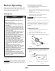
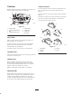
Figure 9
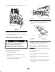
1. Filler neck cap
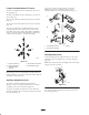
6. Check the fluid level on the dipstick (Fig. 10).
The fluid level should be between the marks on the
dipstick.
m–7467
1
Figure 10
1. Dipstick
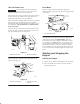
7. If the level is low, add enough fluid to raise it to the
proper level.
8. Install the cap on the filler neck.
Operation
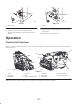
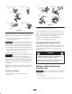
Traction Unit Overview
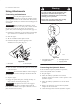
Figure 11 contains a front and back view of the traction unit. Familiarize yourself with all of the traction unit components
listed in Figure 11.
11
1
5
7
8
4
6
2
10
m-7572
m-7571
9
3
Figure 11
1. Track
2. Lift cylinder
3. Cylinder lock
4. Loader arm
5. Hood
6. Auxiliary hydraulic couplers
7. Tilt cylinder
8. Mount plate
9. Control panel
10. Rear access cover
11. Reverse safety plate
Note: Determine the left and right sides of the machine by standing in the operator’s position.