Form No. 3353-734 Rev A TX 420 and TX 425 Compact Utility Loader Model No. 22331—250000001 and Up Model No. 22332—250000001 and Up Operator’s Manual Register your product at www.Toro.
Warning Checking the Oil Level . . . . . . . . . . . . . . . . . . . . Removing Debris from the Traction Unit . . . . . . Checking the Hydraulic Fluid . . . . . . . . . . . . . . . Operation . . . . . . . . . . . . . . . . . . . . . . . . . . . . . . . . . . Traction Unit Overview . . . . . . . . . . . . . . . . . . . . Controls . . . . . . . . . . . . . . . . . . . . . . . . . . . . . . . . Starting and Stopping the Engine . . . . . . . . . . . . Stopping the Traction Unit . . . . . . . . . . . . . . . .
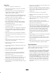
or Service Representative provide exact information about your specific product. The two numbers are stamped into a plate mounted under the hood near the belt drive. Warning Engine exhaust contains carbon monoxide, an odorless, deadly poison that can kill you. For your convenience, write the product model and serial numbers in the space below. Do not run the engine indoors or in an enclosed area. Model No: Serial No. Training • Read the Operator’s Manual and other training material.
Operation • Do not carry a load with the arms raised. Always carry loads close to the ground. • Never run an engine in an enclosed area. • Do not over-load the attachment and always keep the load level when raising the loader arms. Logs, boards, and other items could roll down the loader arms, injuring you. • Only operate in good light, keeping away from holes and hidden hazards. • Be sure all drives are in neutral and parking brake is engaged before starting the engine.
• Disconnect the battery or remove the spark plug wires before making any repairs. Disconnect the negative terminal first and the positive last. Reconnect positive first and negative last. • Raising the loader arms on a slope will affect the stability of the machine. Whenever possible, keep the loader arms in the lowered position when on slopes. • Removing an attachment on a slope will make the rear of the traction unit heavy.
• Battery gases can explode. Keep cigarettes, sparks and flames away from the battery. • Keep your body and hands away from pin hole leaks or nozzles that eject high pressure hydraulic fluid. Use cardboard or paper to find hydraulic leaks; never use your hands. Hydraulic fluid escaping under pressure can penetrate skin and cause injury requiring surgery within a few hours by a qualified surgeon or gangrene may result.
Slope Chart MĆ4402 7
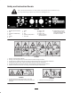
Safety and Instruction Decals Safety decals and instructions are easily visible to the operator and are located near any area of potential danger. Replace any decal that is damaged or lost. 108-4635 1. 2. 3. 4. 5. 6. Read the Operator’s Manual. Fast Continuous variable setting Slow Throttle On 7. 8. 9. 10. 11. Choke Off Fuel Hydraulic oil temperature Hour meter 12. 13. 14. 15. Engine—start Engine—run Engine—stop Warning—read the Operator’s Manual. 16.
4-9950 104-9954 1. Warning—read the Operator’s Manual; maximum load rating of 500 lb. (228 Kg). 1. Warning;crushing hazard of hands or feet—install the cylinder lock. 104-9951 1. Hot surface/burn hazard—wear protective gloves when handling the hydraulic couplers and read the Operator’s Manual for information on handling hydraulic components. 108-4636 1. Auxiliary hydraulics 2. Locked reverse (detent) 3. Forward 4. Neutral (off) 108-4634 1. Traction Control 2. Forward 3. Reverse 4.
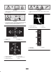
104-9977 1. Loader valve lock, unlocked 2. Loader valve lock, locked 104-9983 1. Hot surface/burn hazard—stay a safe distance from the hot surface. 93-9084 1. Lift point 2. Tie-down point 93-7814 1. Entanglement hazard, belt—stay away from moving parts. 93-6686 1. Hydraulic oil 2. Read the Operator’s Manual.
Setup Activating the Battery 4. Remove filler caps from the battery. Slowly pour electrolyte into each cell until the electrolyte level is up to the lower part of the tube (Fig. 2). Warning 1 Battery posts, terminals, and related accessories contain lead and lead compounds, chemicals known to the State of California to cause cancer and reproductive harm. Wash hands after handling. 2 3 The traction unit is shipped with a dry battery. Purchase bulk electrolyte with 1.
7. Slowly pour electrolyte into each cell until the level is once again up to the upper line on the battery case (Fig. 2) and install covers. 8. Tilt the top of the battery rearward and slide it into the traction unit. Important Do not allow the battery posts to touch the frame or hydraulic lines or it may cause sparks. 9. Secure the battery in chassis with the clamp, bolts, and nuts removed previously (Fig. 1). 10.
Specifications Attachments Many attachments are available for use with the traction unit. These attachments allow you to to perform many different functions with the traction unit such as hauling materials, digging holes, grading, and more. Contact your Toro dealer for a list of all approved attachments and accessories. Specifications and design are subject to change without notice.
Stability Data The following tables list the maximum slope recommended for the traction unit in the positions listed in the tables. Slopes over the listed degree may cause the traction unit to become unstable. The data in the tables assume that the loader arms are fully lowered; raised arms may affect the stability. In each attachment manual is a set of three stability ratings, one for each hill position.
Before Operating Important Do not use methanol, gasoline containing methanol, or gasohol containing more than 10% ethanol because the fuel system could be damaged. Do not mix oil with gasoline. Before operating, check the fuel and oil level, and remove debris from the traction unit. Also, ensure that the area is clear of people and debris. You should also know and have marked the locations of all utility lines.
6. Clean any debris build-up on the engine and in the oil cooler fins with a brush or blower. 2 Important It is preferable to blow dirt out, rather than washing it out. If water is used, keep it away from electrical items and hydraulic valves. Do not use a high-pressure washer. High-pressure washing can damage the electrical system and hydraulic valves or deplete grease. 1 m-5232 m–3219 7. Clean debris from the cooler fan grill on the hood. Figure 4 1. Oil dipstick 8. Close the hood. 2.
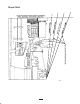
Operation Traction Unit Overview Figure 7 contains a front and back view of the traction unit. Familiarize yourself with all of the traction unit components listed in Figure 7. 6 5 11 10 7 4 8 3 14 2 m-4732 1 9 13 m-8216 12 Figure 7 1. 2. 3. 4. Track Track adjustment chamber Lift cylinder Cylinder lock 5. 6. 7. 8. Loader arms Hood Auxiliary hydraulic couplers Tilt cylinder 9. Mount plate 10. Tie-down/lift loop 11. Control panel 12. Rear access cover 13. Fuel tank 14.
Key Switch Loader Arm/Attachment Tilt Lever The key switch, used to start and stop the engine, has three positions: off, run, and start. To tilt the attachment forward, slowly move the lever to the right (Fig. 10). To start the engine, rotate the key to the start position. Release the key when engine starts and it will move automatically to the run position. To tilt the attachment rearward, slowly move the lever to the left (Fig. 10). To stop the engine, rotate the key to the off position.
1 2 After 50 hours and then every 100 hours thereafter (that is at 150, 250, 350, etc.) the screen displays CHG OIL to remind you to change the engine oil. After every 100 hours, the screen displays SVC to remind you to perform the other maintenance procedures based on a 100, 200, or 400 hour schedule. These reminders come on starting three hours prior to the service interval time and flash at regular intervals for six hours. 3 m–8218 Starting and Stopping the Engine Figure 11 1.
Stopping the Traction Unit Using the Cylinder Lock To stop the traction unit, release the traction control, move the throttle lever to slow (turtle), lower loader arms to the ground, and stop the engine. Set the parking brake and remove the key. Warning The loader arms may lower when in the raised position crushing anyone under them. Caution Install the cylinder lock before performing maintenance that requires raised loader arms.
Using Attachments Warning Important If you are using an attachment with a serial number of 200999999 or earlier, the manual for the attachment may contain information specific to the use of the attachment with other compact utility loader models, such as settings for the flow divider control and speed selector lever and the use of a counterweight on the traction unit. These systems are built into the TX Compact Utility Loader, and you should ignore any references to them.
Securing the Traction Unit for Transport Note: When you connect the attachment male connector first, you will relieve any pressure build up in the attachment. Important roadways. Warning Do not operate or drive the traction unit on Important When transporting the traction unit on a trailer, always use the following procedure: Hydraulic fluid escaping under pressure can penetrate skin and cause injury.
Maintenance Recommended Maintenance Schedule Maintenance Service Interval Maintenance Procedure After the first 50 hours • Change engine oil and filter Grease the traction unit Check engine oil level Check for loose fasteners Inspect the tracks for damage or wear 8 hours • • • • 25 hours • Clean the foam pre-filter and the paper air filter1 • Check hydraulic oil level5 • Inspect hydraulic lines for leaks 100 hours • • • • • • 200 hours • Change hydraulic filter1, 3, 4 • Replace the fuel filter1 •
Caution If you leave the key in the ignition switch, someone could accidently start the engine and seriously injure you or other bystanders. Remove the key from the ignition and disconnect the wire from the spark plug before you do any maintenance. Set the wire aside so that it does not accidentally contact the spark plug. Accessing the Engine and Internal Components 3. Swing the prop rod up and secure it in the bracket on the hood (Fig. 19).
Removing the Front Screen Caution If the engine has been running the heat shield will be very hot and could burn you. 1 Allow the traction unit cool completely before touching the heat shield. 1. Open the hood and remove both side screens. m–7675 Figure 20 2. Loosen the bolts securing the front weight (Fig. 22). 1. Hand knob 3 4 Closing the Rear Access Cover 1 1. Move the rear access cover in place over the back of the traction unit making sure the tabs line up in the slots. 2.
7. Remove the front screen. 1 2 4 4 1 2 3 m–7878 m–5921 Figure 25 Figure 24 1. Nut 2. Oil cooler 1. Front of the control, out of alignment 3. Front screen 4. Shoulder bolts 2. Reference bar 4. If the front of the traction control does not rest square and flush with the reference bar, loosen the flange nut and bolt in the stem of the traction control (Fig. 26). 8. When finished, install the front screen with the 4 bolts removed previously. 9.
1. Drive the traction unit with the traction control against the reference bar, noting which direction the traction unit veers. 1. Lift/support the traction unit so that both tracks are off of the ground. 2. Open the rear access cover; refer to Opening the Rear Access Cover, page 25. 2. Release the traction control. 3. If the traction unit veers to the left, loosen the right jam nut and adjust the tracking set screw on the front of the traction control (Fig. 29). 3.
5. Lightly tap the paper filter on a flat surface to remove dust and dirt (Fig. 32). 1 2 6. Inspect the paper filter for tears, an oily film, and damage to the rubber seal. 4 3 Important Never clean the paper element with pressurized air or liquids, such as solvent, gas, or kerosene. Replace the paper element if it is damaged, or cannot be cleaned thoroughly (i.e., after approximately 100 operating hours). 5 6 7 9 8 1 2 m–7883 m–1213 Figure 30 1. 2. 3. 4. 5.
USE THESE SAE VISCOSITY OILS 7. Remove the old filter (Fig. 34) and wipe the surface of the filter adapter gasket. 10W-30 5W-20, 5W-30 –20 °F 0 –30 °C –20 20 32 40 –10 0 80 60 10 20 100 30 1 40 m–1256 Figure 34 1. Oil filter Changing the Oil 8. Pour new oil of the proper type through the center hole of the filter. Stop pouring when the oil reaches the bottom of the threads. 1. Start the engine and let it run for five minutes. This warms the oil so it drains better. 9.
m–4775 Important Ensure that you only use high-pressure water to wash the track area. Do not use a high-pressure washer to clean the rest of the traction unit. High-pressure washing can damage the electrical system and hydraulic valves or deplete grease. 1 Important Ensure that you fully clean the road wheels, the tension wheel, and the drive sprocket (Fig. 35). The road wheels should rotate freely when clean. Figure 36 1. 2-3/4 inches (7 cm) 1 1.
Replacing the Tracks (TX 420, Model 22331) 11. Turn the tensioning screw counter-clockwise until the distance between the tension nut and the back of the fork tube (Fig. 36) is 2-3/4 inches (7 cm). When the tracks are badly worn, replace them. 12. Align the closest notch in the tension screw to the locking bolt hole and secure the screw with the locking bolt and nut. 1. Lower the loader arms, stop the engine, and remove the key. 2.
8. Remove the nut securing the inner tension wheel and remove the wheel (Fig. 39). 9. Pull the 4 large washers out of the 2 wheels, 1 on each side of each wheel. 10. Clean the old grease and dirt out of the area between where the washers were installed and the bearings inside the wheels, then fill this area on each side of each wheel with grease. 3 11. Install the large washers on the wheels over the grease. 12. Install the inner tension wheel and secure it with the nut removed previously (Fig. 39).
2. Check the gap between the center and side electrodes (Fig. 43). 9. Install each track guide to the traction unit frame using the fasteners you removed previously. Torque the bolts to 67 to 83 ft-lb (91 to 112 N⋅m). 3. Bend the side electrode (Fig. 43) if the gap is not correct. 10. Install the tracks; refer to Replacing the Tracks, page 32. 2 3 1 Servicing the Spark Plugs 0.030 inch (0.76 mm) Check the spark plugs after every 200 operating hours.
1 2 m–7673 Figure 46 1. Filter m-4732 Figure 44 2. Hose clamp 6. Place a drain pan under the fuel lines to catch any leaks, then remove the filter from the fuel lines. 7. Slide the fuel lines on the new fuel filter fittings, ensuring that the arrow on the filter points away from the fuel line coming from the fuel tank and toward the line going to the fuel pump. Important m–4056 Never install a dirty filter. 8. Move the hose clamps close to the filter. Figure 45 9.
Servicing the Hydraulic System Warning Hydraulic fluid escaping under pressure can penetrate skin and cause injury. Fluid injected into the skin must be surgically removed within a few hours by a doctor familiar with this form of injury or gangrene may result. Replacing the Hydraulic Filter Important Do not substitute an automotive oil filter or severe hydraulic system damage may result.
6. Place a large drain pain (capable of holding 15 US gallons) under the drain plug on the front of the traction unit (Fig. 49). Warning Hydraulic fluid escaping under pressure can penetrate skin and cause injury. Fluid injected into the skin must be surgically removed within a few hours by a doctor familiar with this form of injury or gangrene may result. Note: The drain plug is located behind the front weight, under the muffler.
1 2 Warning Charging the battery produces gases that can explode. 3 Never smoke near the battery and keep sparks and flames away from battery. 1262 Figure 50 1. Filler caps 2. Lower part of tube 3. Plates Cleaning the Chassis Over time, the chassis under the engine collects dirt and debris that must be removed. Using a flashlight, open the hood and inspect the area under the engine on a regular basis.
20. Slide the tank all the way into the traction unit. 9. Place a clamp on the fuel line, 2 inches from where it comes out of the fuel tank. Important The fuel line and wires must be away from the engine pulleys and the frame. 10. Slide the fuel tank to the rear (Fig. 51). 11. Disconnect the fuel line. 21. Replace the rear panel and secure it with the six bolts and nuts removed previously (Fig. 51). 12. Disconnect the two wires leading to the right side of the tank (Fig. 52). 22.
A. Add a petroleum based stabilizer/conditioner to fuel in the tank. Follow mixing instructions from stabilizer manufacturer. (1 oz. per US gallon). Do not use an alcohol based stabilizer (ethanol or methanol). Note: A fuel stabilizer/conditioner is most effective when mixed with fresh gasoline and used at all times. B. Run the engine to distribute conditioned fuel through the fuel system (5 minutes). C. Stop the engine, allow it to cool and drain the fuel tank using a pump type syphon. D.
Troubleshooting PROBLEM Starter does not crank POSSIBLE CAUSES CORRECTIVE ACTION 1. Battery is dead. 1. Charge the battery. 2. Electrical connections are corroded or loose. 2. Check electrical connections for good contact. 3. Relay or switch is defective. 3. Contact Authorized Service Dealer. 1. Fuel tank is empty. 1. Fill fuel tank with gasoline. 2. Choke is not on. 2. Move choke lever fully forward. 3. Air cleaner is dirty. 3. Clean or replace air cleaner element. 4.
Schematics Electrical Schematic 42
Hydraulic Schematic 43 16 17 X 1 CV1 10 X 1 P 13 X 2 13 2RV4 A DISPLACEMENT A 16 M1 PORT B 0.73 CU IN 12 CC 0.36 CU IN 6 CC 32.3 CU IN 528 CC 0–1.28 CU IN 21 CC P 10 X 1 10 X 1 16 2465 PSI 3000 PSI 3050 PSI 2900 PSI 5 PSI 170 BARS 207 BARS 210 BARS 200 BARS .35 BARS BARS 13 X 2 T 64 17 LPM 42.4 21.0 11.2 5.5 GPM 10 P 8X1 P ** FLOWRATE CALCULATED AT 3100 RPM AND 98% EFFICIENCY.
The Toro Warranty A One-Year Limited Warranty Conditions and Products Covered Items and Conditions Not Covered The Toro Company and its affiliate, Toro Warranty Company, pursuant to an agreement between them, jointly warrant your Toro Product (“Product”) to be free from defects in materials or workmanship.